


4-2
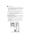
Making Network Connections
4
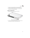
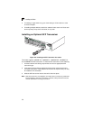
2. If the device is a PC card and the switch is in the wiring closet, attach the other
end of the cable segment to a modular wall outlet that is connected to the wiring
closet. (See “Network Wiring Connections” on page 4-2.) Otherwise, attach the
other end to an available port on the switch.
Make sure each twisted pair cable does not exceed 100 meters (328 ft) in
length.
3. As each connection is made, the Link LED (on the switch) corresponding to
each port will light to indicate that the connection is valid.
Note: Avoid using flow control on a port connected to a hub unless it is actually required
to solve a problem. Otherwise back pressure jamming signals may degrade
overall performance for the segment attached to the hub.
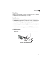
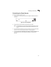
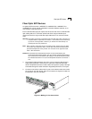
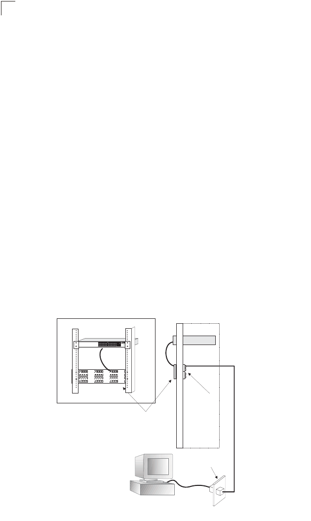
Network Wiring Connections
Today, the punch-down block is an integral part of many of the newer equipment
racks. It is actually part of the patch panel. Instructions for making connections in the
wiring closet with this type of equipment follows.
1. Attach one end of a patch cable to an available port on the switch, and the other
end to the patch panel.
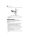
2. If not already in place, attach one end of a cable segment to the back of the
patch panel where the punch-down block is located, and the other end to a
modular wall outlet.
3. Label the cables to simplify future troubleshooting. See “Cable Labeling and
Connection Records” on page 4-5.
Figure 4-2 Network Wiring Connections
Console
Power
RPU
Diag
Master
Link
ID
Stack
12
3
4
5
678910
1112
15
14
13 18
17
16
21
2019
24
23
22
25
26
25262728
Console
27
28
Power
RPS
Diag
ES3628EA
Equipment Rack
(side view)
Network Switch
Patch Panel
Punch-Down Block
Wall
witch10/100
6724L3
E
S
4
5
2
4
C