


54 Chapter 3
Main Unit Disassembly Process
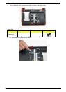
IMPORTANT: Cable paths and positioning may not represent the actual model. During the removal and
replacement of components, ensure all available cable channels and clips are used and that the cables are
replaced in the same position.
NOTE: The product previews seen in the disassembly procedures may not represent the final product color or
configuration.
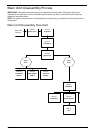
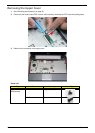
Main Unit Disassembly Flowchart
Remove
Mainboard
Remove
Switch Cover
Remove
Keyboard
Remove
Upper Cover
Remove
LCD Module
ove External
dules before
roceeding
Remove
TouchPad
Bracket
Upper
Cover
Lower
Cover
Remove
Left Speaker
Module
Remove
CPU
Remove
RTC Battery
Remove
Thermal Module
Remove
Right Speaker
Module