Chapter 3 62
2. See “Removing the Middle Cover” on page 53.
3. See “Removing the Keyboard” on page 53.
4. See “Removing the Power Board” on page 58.
5. See “Removing the Upper Case Assembly” on page 58.
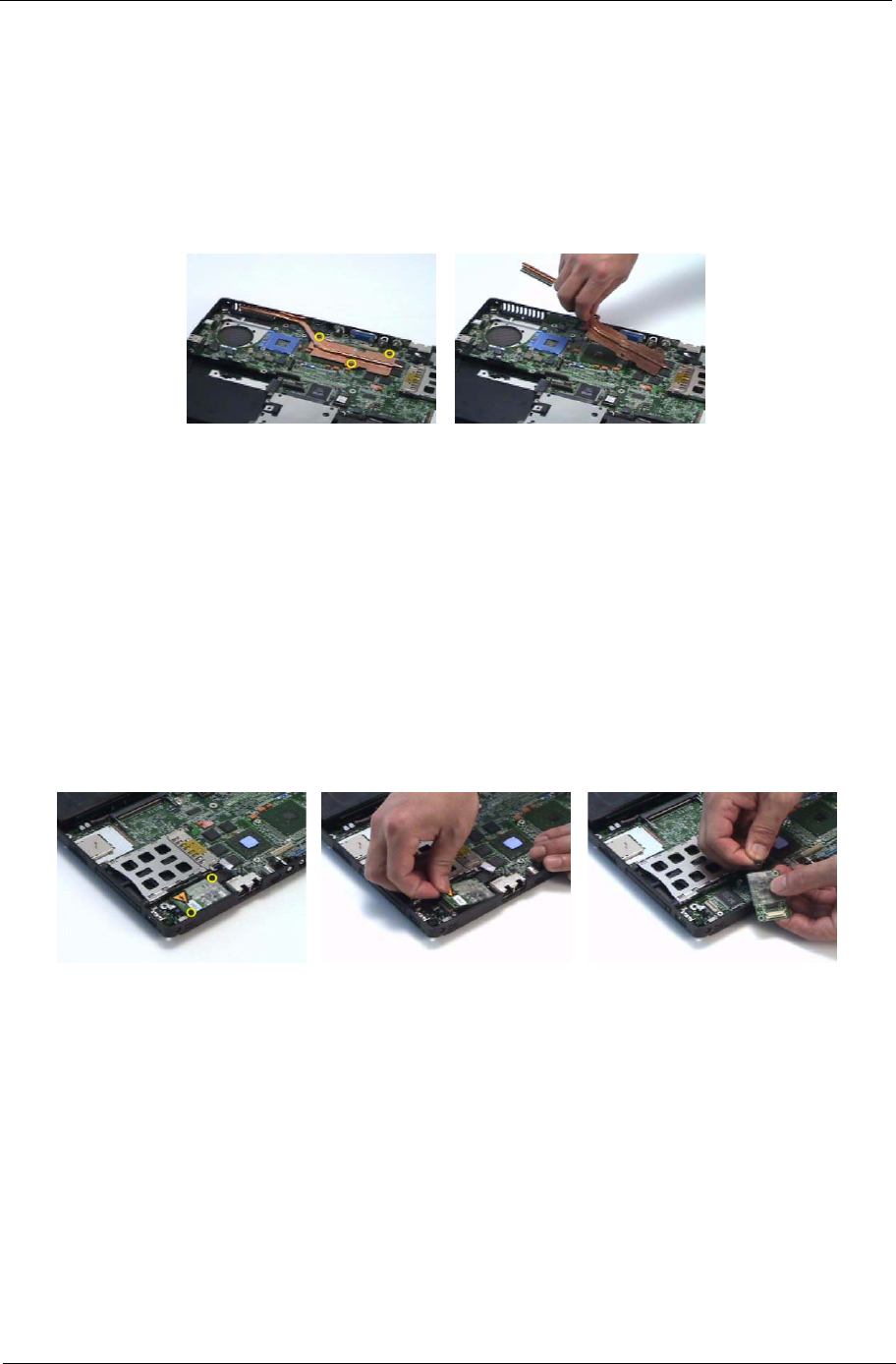
6. Remove the three screws securing the VGA thermal module.
7. Then detach the VGA thermal module.
Removing the Modem Board
1. See “Removing the Battery” on page 50.
2. See “Removing the Middle Cover” on page 53.
3. See “Removing the Keyboard” on page 53.
4. See “Removing the Power Board” on page 58.
5. See “Removing the Upper Case Assembly” on page 58.
6. Remove the two screws securing the modem board.
7. Disconnect the modem board connector.
8. Disconnect the modem board cable then remove the board.
Removing the Main Board
1. See “Removing the Battery” on page 50.
2. See “Removing the Middle Cover” on page 53.
3. See “Removing the Keyboard” on page 53.
4. See “Removing the Power Board” on page 58.
5. See “Removing the Upper Case Assembly” on page 58.
6. See “Removing the Speaker Set” on page 60.
7. See “Removing the SW DJ Board Assembly” on page 60.
8. See “Removing the Audio Board” on page 61.
9. See “Removing the VGA Thermal Module” on page 61.


