


71 Chapter 3
3. See “Removing the Keyboard” on page 63.
4. See “Removing the Upper Case Assemly” on page 65.
5. See “Removing the Fan” on page 63.
6. See “Removing the Thermal Module” on page 64.
7. See “Removing the VGA Thermal Plate” on page 67.
8. See “Removing the CPU Heatsink Plate” on page 67.
9. See “Removing the Second Fan Bracket” on page 68.
10. See “Removing the ODD Module(2)” on page 68.
11. See “Removing the HDD Bracket” on page 69.
12. See “Removing the Main Board” on page 69.
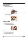
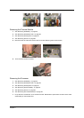
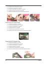
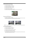
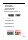
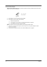
13. Remove the four hex screws to detach the I/O port bracket from the main board.
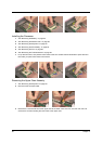
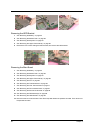
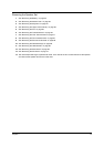
Removing the PCMCIA Slot
1. See “Removing the Battery” on page 52.
2. See “Removing the Middle Cover” on page 56.
3. See “Removing the Keyboard” on page 63.
4. See “Removing the Upper Case Assemly” on page 65.
5. See “Removing the Fan” on page 63.
6. See “Removing the Thermal Module” on page 64.
7. See “Removing the VGA Thermal Plate” on page 67.
8. See “Removing the CPU Heatsink Plate” on page 67.
9. See “Removing the Second Fan Bracket” on page 68.
10. See “Removing the ODD Module(2)” on page 68.
11. See “Removing the HDD Bracket” on page 69.
12. See “Removing the Main Board” on page 69.
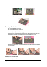
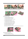
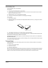
13. Remove the four screws that secure the PCMCIA slot, then remove the PCMCIA slot from the lower case.