


Chapter 3 45
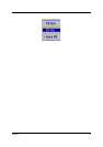
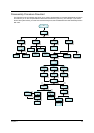
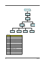
Disassembly Procedure Flowchart
The flowchart on the succeeding page gives you a graphic representation on the entire disassembly sequence
and instructs you on the components that need to be removed during servicing. For example, if you want to
remove the system board, you must first remove the keyboard, then disassemble the inside assembly frame in
that order.
Start
Battery
HDD Module Middle Cover
HDD Carrier Keyboard
M*2
Power Button
DIMM Cover
Memory
M*2
LCD Module
ODD Module
M*1
P*4
M*1
HDD Cover
G*4
J*2
Q*4
HDD Carrier
SUB Assy
M*2
ODD
Optical Device
Bracket
Optical Device
Holder
Optical Device
Board
M*1
Launch Board
L*1
MDC Cover
Plate
Thermal Plate
Mini PCI
Cover
P*2 P*1 K*2
MDC Card
Thermal
Module
Mini PCI
Wireless
Board
*4
CPU
Lower Case
ASSY
LED Cable
O*1
Main Board Lower Case
F*2
I*2
PCMCIA Slot
Hinge Saddles
Upper Case
Support w/
FPC
Upper Case
ASSY
N*3
O*1
Touchpad
M*5
Shielding
Speaker Set
M*2
Wireless
Antenna
P*1
K*1
M*1
M*3
P*14
P*4
G*4