


50 Chapter 3
External Module Disassembly Process
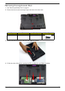
IMPORTANT: The outside housing and color may vary from the mass produced model.
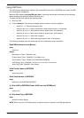
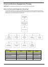
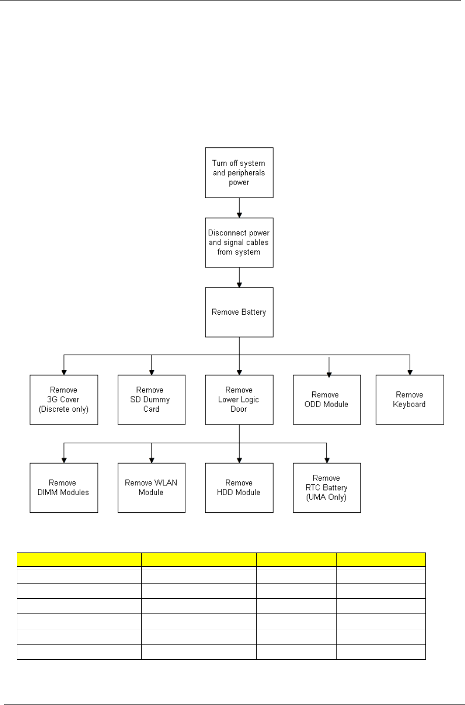
External Modules Disassembly Flowchart
The flowchart below gives you a graphic representation of the external module disassembly sequence and
instructs you on the components that need to be removed during servicing. For example, if you want to remove
the keyboard, you must first remove the switch board.
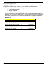
Screw List
Step Screw Quantity Part No.
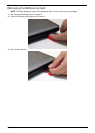
ODD Module M 2.5*8 1 86.R4F02.001
ODD Bracket M2*3 2 86.R4F02.004
Logic lower door M2.5*8 2 86.R4F02.004
3G Cover M2.5*8 1 86.R4F02.004
WLAN Module M2*3 1 86.R4F02.001
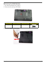
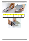
HDD Carrier M3*3 4 86.R4F02.008