3
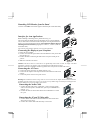
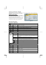
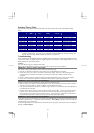
Detaching LCD Monitor from Its Stand
Unscrew screws n the swivel base support column and pull it from main body.
Figure 1-3
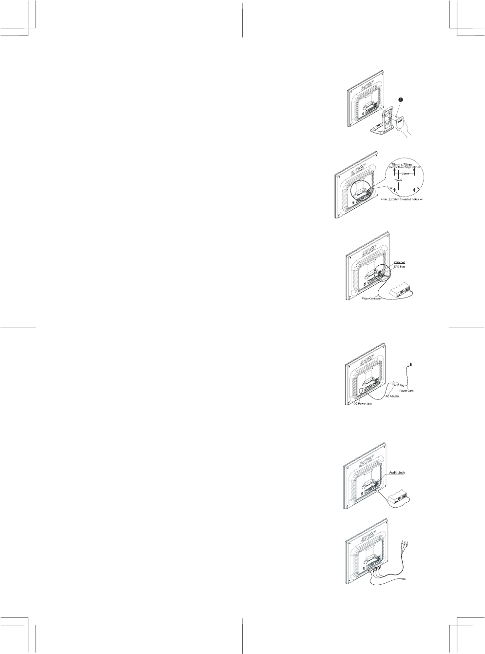
Interface for Arm Applications
Before installing to mounting device, please refer to Fig.1-3.
The rear of this LCD display has four integrated 4 mm, 0.7 pitches threaded
nuts, as well as four 5 mm access holes in the plastic covering as illustrated in
Figure 1-4. These specifications meet the VESA Flat Panel Monitor Physical
Mounting Interface Standard (paragraphs 2.1 and 2.1.3, version 1, dated 13
November 1997).
Note :Please using Ø 4mm x 8mm (L) screw for this application
Figure 1-4
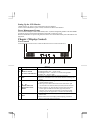
Connecting the Display to your Computer
1. Power off your computer.
2. Connect one end of the signal cable to the LCD Monitor’s VGA port or DVI
port.(See Fig 1-5)
3. Connect the other end of the signal cable to the VGA port or DVI port on
your PC.
4. Make sure connection are secure.
Figure 1-5
Attention: This device must be connected to an off-the-shelf video cable in order to comply with FCC
regulations. A ferrite-core interface cable is included in the LCD Monitor package.
This device will not be in compliance with FCC regulations when a non-ferrite-core video cable is used.
Connecting the AC Power
1. Connect the power cord to the AC adapter.(See Fig. 1-6)
2. Connect the AC adapter’s DC output connector to the DC Power Jack of the
monitor.
3. Connect the power cord to an AC power source.
Figure 1-6
Warning:We recommand to install a “Surge Protector” device between the AC Adapter and the electrical wall outlet
for adding protection against power surges to prevent the errects of sudden voltage variations from reaching the LCD
Monitor. Sudden power surges may damage your monitor.
Connecting the Audio Cable
1. Connect the audio cable to the " LINE OUT " jack on your PC's audio
card or to the front panel's “AUDIO OUT” jack of your CD ROM drive.
(See Fig. 1-7)
2. Connect the other end of the audio cable to the LCD Monitor's " LINE
IN " jack.
Figure 1-7
Connecting the AV and S-Video cable
1. Connect the AV cable to RCA Jack and follow the color and the other
side connect to AV source.
2. Connect the S-Video cable from main body to AV source.
Figure 1-8