


Chapter 5 72
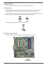
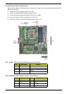
Connecting Case Components
After you have installed the motherboard into a case, you can begin connecting themotherboard components.
Refer to the following:
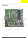
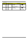
1. Connect the CPU cooling fan cable to CPU_FAN.
2. Connect the standard power supply connector to ATX1.
3. Connect the case switches and indicator LEDs to the F_PANEL.
4. Connect the system cooling fan connector to SYS_FAN.
5. Connect the auxiliary case power supply connector to ATX_12V.
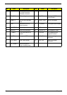
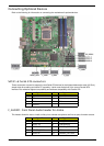
CPU_FAN1: CPU Cooling FAN Power Connector
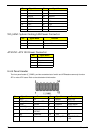
ATX_POWER: ATX 24-pin Power Connector
Pin Signal Name Function
1 GND System Ground
2 +12V Power +12V
3 Sense Sensor
4PWM PWM
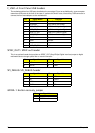
Pin Signal Name Pin Signal Name
1 +3.3V 13 +3.3V
2 +3.3V 14 -12V
3 Ground 15 Ground
4 +5V 16 PS_ON