


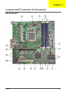

71 Chapter 5
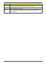
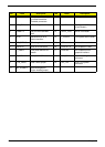
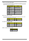
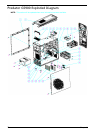
F_USB1~4: Front Panel USB headers
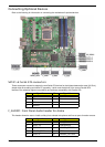
The motherboard has four USB ports installed on the rear edge I/O port array.Additionally, some computer
cases have USB ports at the front of the case. If youhave this kind of case, use auxiliary USB connector to
connect the front-mountedports to the motherboard.
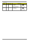
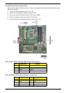
SPDIF_OUT1: SPDIF out header
This is an optional header that provides an SPDIF_OUT (Sony/Philips Digital Inter-face) output to digital
multimedia device through optical fiber or coaxial connector.
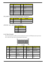
SPI_DEBUG: SPI_DEBUG header
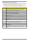
GPIO0~1: Button recovery jumper
Pin Signal Name Function
1 USBPWR Front Panel USB Power
2 USBPWR Front Panel USB Power
3 USB_FP_P0- USB Port 0 Negative Signal
4 USB_FP_P1- USB Port 1 Negative Signal
5 USB_FP_P0+ USB Port 0 Positive Signal
6 USB_FP_P1+ USB Port 1 Positive Signal
7 GND Ground
8 GND Ground
9 Key No pin
10 USB_FP_OC0 NC
Pin Signal Name Pin Signal Name
1+5V 2KEY
3 SPDIF 4 GND
Pin Signal Name Pin Signal Name
1CS 2WP
3DI 4HOLD
5VCC 6CLK
7GND 8DO
Pin Signal Name
1GP36(GP16)
2GND