


Chapter 3 51
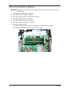
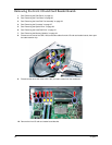
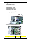
Removing the Mainboard
1. See “Removing the Side Panel” on page 34.
2. See “Removing the Front Bezel” on page 35.
3. See “Removing the Heat Sink Fan Assembly” on page 36.
4. See “Removing the Processor” on page 37.
5. See “Removing the Optical Drive” on page 38.
6. See “Removing the Hard Disk Drive” on page 41.
7. See “Removing the Memory Modules” on page 44.
8. See “Removing the VGA Card” on page 46.
9. See “Removing the TV Tuner Card” on page 45.
10. See “Removing the Front I/O and Card Reader Boards” on page 48.
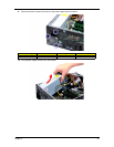
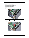
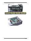
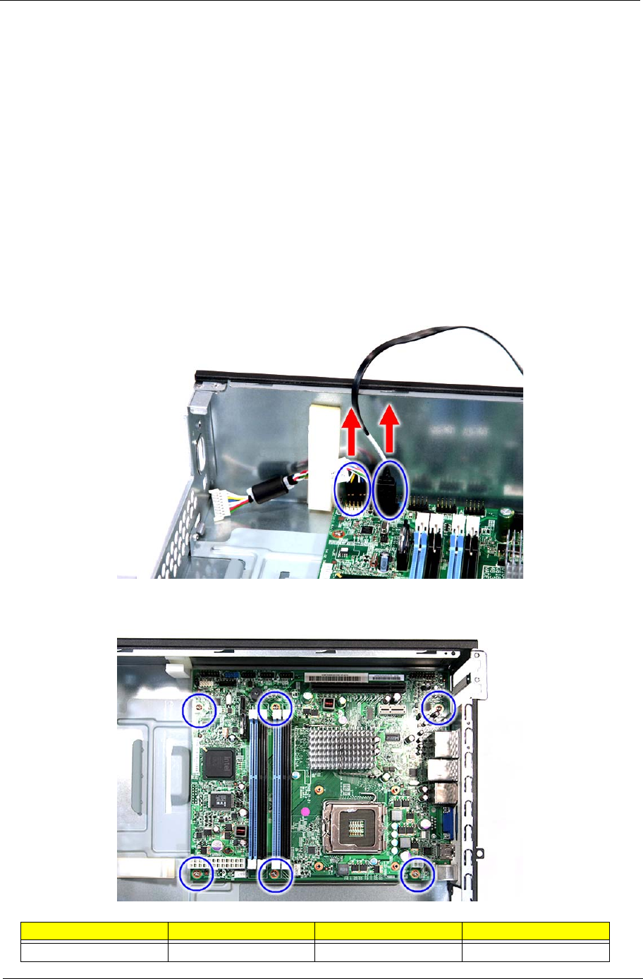
11. Disconnect the LED and SATA cable from the mainboard.
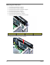
12. Remove the six screws (D) that secure the mainboard to the chassis.
Screw (Quantity) Color Torque Part No.
#6-32 L6 NI (6) Silver 5.7 to 6.3 kgf-cm 86.00J44.C60