


MEASUREMENT
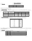
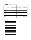
1ǃVoltage check
Measuring point Voltage Description
11VļGND
11.0Vf5%
AC plug should be connected
5VļGND
5.0Vf5%
AC plug should be connected
Note: Measurement with no load is possible.
2ǃMotor operation check
(PCN8.1~4)
Apply the voltages shown below to the terminals of the harness connected to connector PCN8 on the 2000UL PCB ass’y to make sure
that the motor runs properly.
Applied voltage
Motor Operation
Pin 1(orange) Pin 2(green) Pin 3(red) Pin 4(green)
LF Motor(A motor) Pulling 4~9V GND ----- -----
LF Motor(A motor) Ejection GND 4~9V ----- -----
CR Motor(B motor)
Changing red and black
ribbons.(Continuous)
----- ----- 4~9V GND
CR Motor(B motor) Head feed ----- ----- GND 4~9V
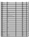
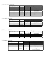
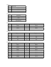
3ǃHead resistance measurement (PCN7.1~12)
Measure the head resistance at the terminals of the harness connected to connector PCN7 on the 2000UL PCB ass’y.
Measuring point(PIN NO. of PCN7) Resistances
1ė8
2ė8
3ė8
4ė8
5ė8
6ė8
7ė8
9ė8
10ė8
11ė8
12ė8
Open
3.0f¡
3.0f¡
3.0f¡
3.0f¡
3.0f¡
Short
3.0f¡
3.0f¡
3.0f¡
3.0f¡
Note˖If the head resistance is less then the values shown aboveˈthe head pin drive circuit may also be defectiveDŽReplace the head and
repair the 2000UL PCB ass’y.
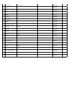
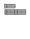
4ǃSensors circu
it
There are five sensorsDŽtheir functions are show below:
Name CPU port Functions
E-03 R80 D etects the right-up edge of an inserted time card.
E-05 R81 D etects the left-up edge of an inserted time card.
E-37 D1 Detects the operating condition of the LF motor.
E-38 D0 Detects the operating condition of the CR motor.
E-30 R73 Check whether the head is at the home position(left end of the machine).