


26 SBC-596/599 User's Manual
COM-port connectors (CN13, CN17)
The SBC-596/599 has two serial ports, COM1 and COM2, to
provide connections for serial devices (a mouse, etc.) or a
communication network. You can find the pin assignments for
the COM port connectors in Appendix B.
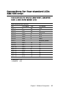
The IRQ and the address range for COM1, 2, are fixed. However,
if you wish to disable the port or change these parameters later
you can do this in the system BIOS setup. The table below shows
the settings for the SBC-599 Series serial ports.
SBC-596/599 port default settings
Port Address Range Interrupt
COM1 3F8~3FF IRQ4
COM2 2F8~2FF IRQ8
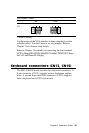
Printer port connector (CN14)
Normally, the parallel port is used to connect the card to a printer.
The SBC-596/599 includes a multi-mode (ECP/EPP/SPP)
parallel port, accessed through CN14, a 26-pin flat-cable
connector. You will need an adapter cable if you use a traditional
DB-25 connector. The adapter cable has a 26-pin connector on
one end and a DB-25 connector on the other.
The parallel port is designated as LPT1 and can be disabled or
changed to LPT2 or LPT3 in the system BIOS setup.
The parallel port interrupt channel is designated to be IRQ7.
You can select ECP/EPP DMA channel via BIOS setup.
IR connector (CN15)
This connector supports the optional wireless infrared transmit-
ting and receiving module. This module mounts on the system
case. You must configure the setting through BIOS setup.