


20 SBC-596/599 User's Manual
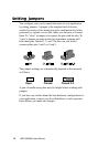
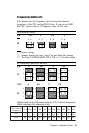
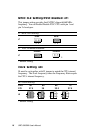
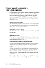
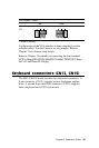
Front panel connectors
(CN1,CN2,CN3,CN4)
You may want to install external switches to monitor and control
the SBC-596/599. These features are optional —install them
only if you need them. The front panel connectors include a
speaker connector (CN1), a HDD LED connector (CN2), an
input switch (CN3) for resetting the card, and a keyboard lock
connector (CN4).
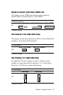
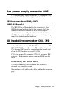
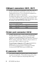
Speaker connector (CN1)
The SBC-596/599 can drive an 8 W speaker at 0.5 watts. Ensure
that alternatives to this specification do not overload the card.
Close pins 3 and 4 to enable the buzzer.
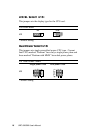
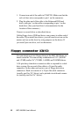
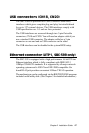
HDD LED connector (CN2)
The LED indicator for hard disk access is an active low signal (24
mA sink rate).
Reset switch (CN3)
If you install a reset switch, it should be an open single pole
switch. Momentarily pressing the switch will activate a reset. The
switch should be rated for 10 mA, 5 V.
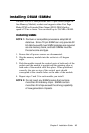
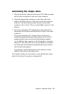
Power LED/keyboard lock connector (CN4)
You can connect an LED to indicate if the CPU card is powered
on. Pin 1 of CN4 supplies power to the LED, and pin 3 is the
ground.
You can use a switch (or a lock) to disable the keyboard. In this
state, the PC will not respond to any input from the keyboard.
This is useful if you don’t want anyone to change or stop a
running program. Simply connect the switch between pin 4 and
pin 5 of CN4.
If you need to make your own cable, you can find the pin assign-
ments for the board’s connector in Appendix B.