


ADCP-92-063 • Issue 1 • May 2005
Page 9
© 2005, ADC Telecommunications, Inc.
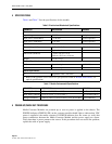
b. The IEEE Standard ANSI/TIA-568-B for Ethernet 10/100BaseT(X) requires that two
twisted pairs be used and that one pair is connected to pins 1 and 2, and that the second
pair is connected to pins 3 and 6.
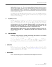
c. The IEEE Specification Standard ANSI/TIA-568-B for Ethernet 1000BaseT requires
that four twisted pairs are used. One pair is connected to pins 1 and 2, pair two is
connected to pins 3 and 6, pair three is connected to pins 4 and 5, and pair four is
connected to pins 7 and 8.
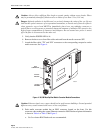
9. Connect Ethernet RJ45 patchcord to RJ45 receptacle on the converter module.
10. Verify that the front panel LEDs are active. Link LEDs are not lighted if there is no
Ethernet or optical signal present.
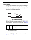
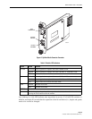
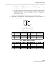
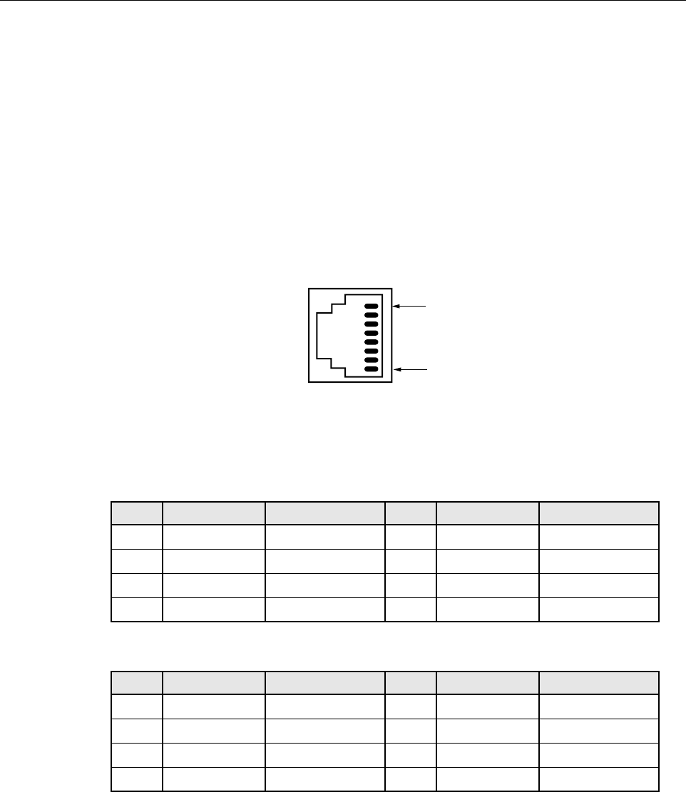
Figure 5. RJ45 Connector Wiring
Table 4. 10/100BaseT(X) Ethernet RJ45 Connector
PIN # SIGNAL NAME FUNCTION PIN # SIGNAL NAME FUNCTION
1 TX+ Transmit Data 2 TX– Transmit Data
3 RX+ Receive Data 4 --- Not used
5 --- Not used 6 RX– Receive Data
7 --- Not used 8 --- Not used
Table 5. 1000BaseT Ethernet RJ45 Connector
PIN # SIGNAL NAME FUNCTION PIN # SIGNAL NAME FUNCTION
1 BD1+ Bidirectional 2 BD1– Bidirectional
3 BD2+ Bidirectional 4 BD3+ Bidirectional
5 BD3– Bidirectional 6 BD2– Bidirectional
7 BD4+ Bidirectional 8 BD4– Bidirectional
RJ-JACK
PIN 1
PIN 8
11899-A