


LTPH-UM-1234-01 PG-Flex Deployment
HDU-409 Lists 1, 2, and 3 April 30, 2003 7
PG-FLEX DEPLOYMENT
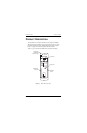
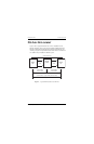
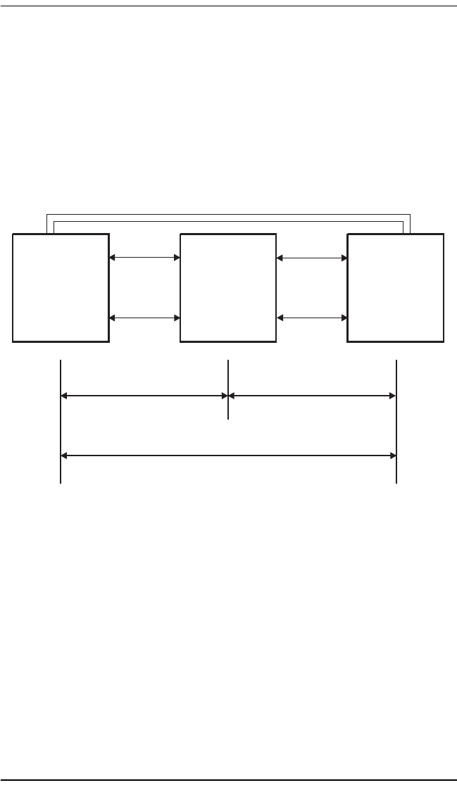
Figure 2 shows a typical HDU-409 List 2 or List 3 installation for the
PG-Flex subscriber carrier system. For each doubler installed between the
PG-Flex Central Office Terminal (COT) and Remote Terminal (RT), two
auxiliary power pairs are required between the COT and RT. A maximum of
two doublers may be installed in a PG-Flex system.
Figure 2. Typical HDU Installation with PG-Flex
PG-Flex
RT
HDSL
HDU-409
Doubler
HDSL
PG-Flex
COT
9,000' 26 AWG
12,000' 24 AWG
9,000' 26 AWG or 12,000' 24 AWG (without Doubler)
9,000' 26 AWG
12,000' 24 AWG
Span 1
Auxiliary Power Pairs
Span 2
H0079-A