


Appendix A - Functional Description LTPH-UM-1234-01
26 April 30, 2003 HDU-409 Lists 1, 2, and 3
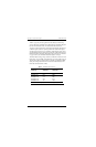
Table 8 on page 26 provides a guide for the loss that occurs when using
various cable gauges at 196 kHz and 135Ω. It applies to the HDSL cable pairs
between the COT and the HDU, and between the HDU and the RT.
To achieve optimum performance, make the electrical length (196 kHz loss)
of all HDU spans as close to equal as possible. This results in the highest
operating loop margins. If it is not possible to make all spans equal, choose
span lengths that reduce the total power consumption of the CPT that powers
the HDU. Do this by minimizing the length of Span 1 and Span 2. Use Table 8
on page 26 when you calculate the electrical length of each span.
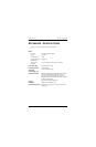
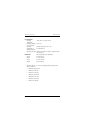
The HDU-409 has a range of up to 35 dB loss at 196 kHz on each of the four
HDSL loops. A list of HDSL signal cable losses for various cable gauges at
196 kHz and 135Ω is provided in Table 8. The table is applicable to HDSL
cable pairs running between the HLU and the HDU-409 and between the
HDU-409 and another HDU or HRU.
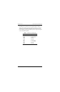
Table 8. HDSL Signal Cable Loss
Cable Gauge
Ω per kFt
(0.3048 km)
Loss @ 196 kHz
(dB per kFt)
(a)
(a) Add 3 dB for each bridged tap and 1 dB for each cable gauge change.
26 AWG/0.4 mm 83.3 3.880
24 AWG/0.51 mm 51.9 2.841
22 AWG/0.61 mm 32.4 2.177
19 AWG/0.91 mm 16.1 1.535