


Installing the BNC Panel LTPS-UM-8013-03
8 August 30, 2002 D3LX CO and RMT Modules
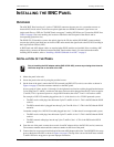
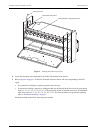
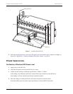
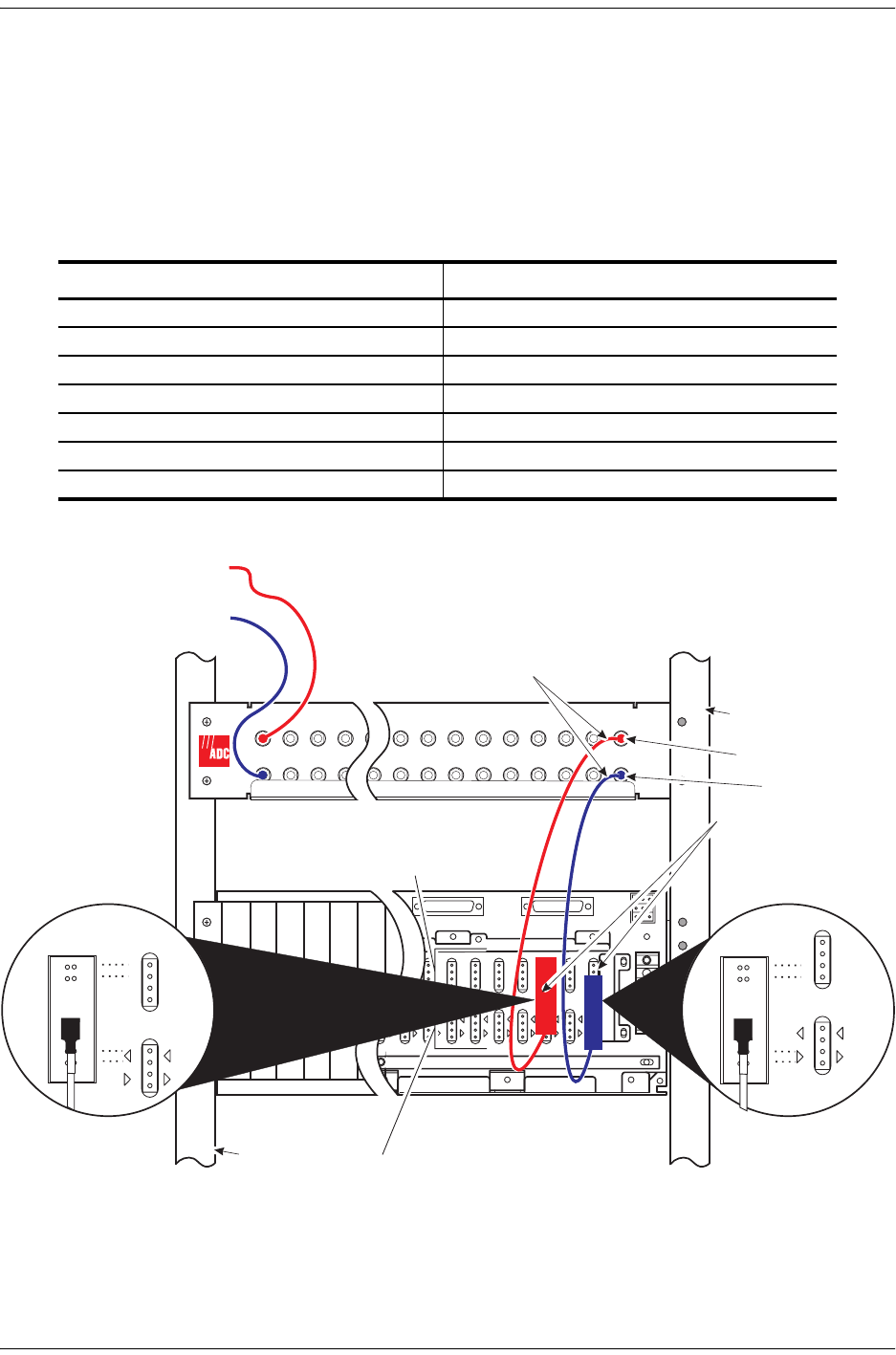
6 From the rear of the panel, connect the coax end of an ADC adapter cable to the DS3 OUT (transmit).
connector. The connector number must match the connector number on the front of the panel.
7 Connect the wire-wrap conversion block end of the same ADC adapter cable to the T and R EQUIP wire-wrap
posts on the back of the LEC as shown in Figure 4 on page 8. The top of the conversion block mates with the
T1 and R1 LINE wire-wrap posts to prevent improper connection.
8 Repeat this entire procedure for each D3LX module installed.
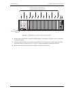
Figure 4. Mounting the BNC Panel and Connecting ADC Adapter Cables (LEC Shown)
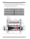
Table 2. Tip and Ring Assignments for Protection Switching Applications
Working Card Slot TX/RX BNC Connector Pair Protect Card Slot TX/RX BNC Connector Pair
1-1 1/15 1-3 2/16
2-1 3/17 2-3 4/18
3-1 5/19 3-3 6/20
4-1 7/21 4-3 8/22
5-1 9/23 5-3 10/24
6-1 11/25 6-3 12/26
7-1 13/27 7-3 14/28
2 3 4 9 8 56 4 3 2 1
19 18 17 16 1523 22 2016 17 18 19
BNC panel - front
T
R
T1
R1
L1
L2
2-4
T
R
T1
R1
T
R
T1
R1
L1
L2
2-3
PORT 2 DTE RS-232
T
R
T1
R1
T
R
T1
R1
L1
L2
2-2
T
R
T1
R1
T
R
T1
R1
L1
L2
2-1
T
R
T1
R1
T
R
T1
R1
L1
L2
1-4
T
R
T1
R1
L1
L2
1-3
T
R
T1
R1
T
R
T1
R1
L1
L2
1-2
T
R
T1
R1
T
R
T1
R1
L1
L2
1-1
T
R
T1
R1
SHIELD GND
FRAME GND
PORT 3 DTE RS-232
A
B
A
B
–48V
RTN
DS3 in
21
Loop Extender - front
LINE wire-wrap row
CO rack - rear
1
15
(transmit)
DS3 in
(receive)
DS3 out
BNC panel - rear
DS3 out
7
T
R
T1
R1
CO rack - front
Loop Extender - rear
EQUIP wire-wrap row
T
R
T1
R1
T
R
T1
R1
1-1
T
R
T1
R1
L1
L2
ADC adapter
cables
(conversion block end)
ADC adapter
cables (coax end)
T
R
T1
R1
1-3
T
R
T1
R1
L1
L2