


ADCP-50-404 • Issue 2 • November 1998
Page 5
© 1998, ADC Telecommunications, Inc.
5. OUTPUT CABLE ASSIGNMENTS
Output from the DMPS-l0CE Power Supply is delivered via a 6 foot, 16 gauge cable,
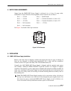
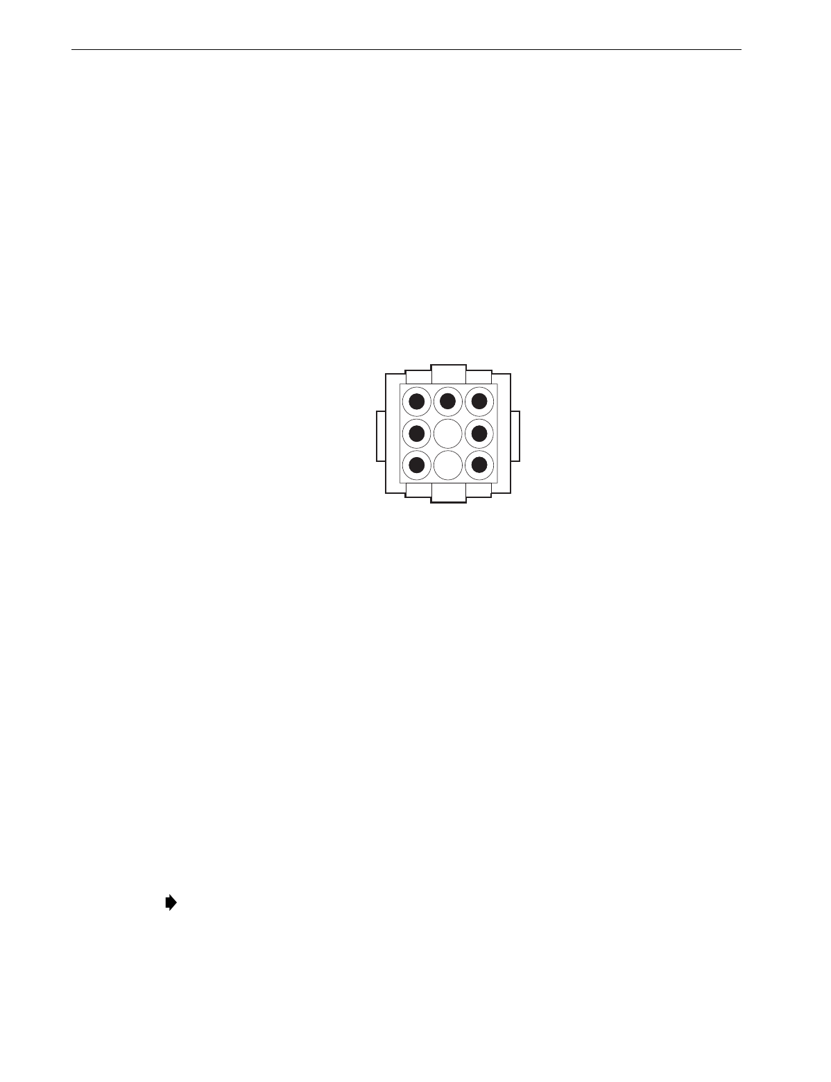
terminated in a 9-pin connector. Pin assignments on the connector are as follows:
Pin 1 — +5 Volts Pin 6 — Earth Ground
Pin 2 — +5 Volts Pin 7 — Common Ground for +5 and ± 12 V
Pin 3 — +12 Volts Pin 8 — Common Ground for +5 and ± 12 V
Pin 4 — No Connection Pin 9 — –12 Volts
Pin 5 — No Connection
See Figure 3 for sketch of the 9-pin connector.
4
4555-A
6
3
9
1
7
28
Figure 3. 9-Pin Connector
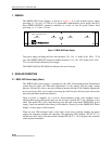
6. INSTALLATION
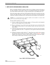
6.1 DMPS-10CE Power Supply Installation
Remove each item from its shipping container and inspect the units for signs of damage. If
there are any damaged or missing parts, immediately file a claim with the commercial
common carrier or its agent, and notify ADC Telecommunications, Inc.
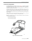
Normally, the ADC DMPS-10CE Power Supply is shipped with the standard single power
unit installed. Additional DMPS-10EXP/CE expansion modules are shipped in separate
containers. Occasionally, a power supply may be shipped with expansion modules installed. In
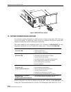
either case, installation of the power supply involves positioning the unit in the desired rack
space, near an ac utility outlet, and securing it with the mounting hardware normally used on
the mounting rack.
Note:
The DMPS-10CE Power Supply requires air for convection cooling. Air holes in
the top cover and bottom cover allow air to flow through the power supply chassis. For
this reason, be sure to mount the DMPS-10CE Power Supply in such a fashion as to
leave at least half of the top and bottom surfaces open to air movement.