


ADCP-50-404 • Issue 2 • November 1998
Page 6
© 1998, ADC Telecommunications, Inc.
7. DMPS-10EXP/CE EXPANSION MODULE INSTALLATION
Remove the DMPS-10EXP/CE expansion module from its shipping container and inspect it
for signs of damage or missing parts. If there are any damaged or missing parts, immediately
file a claim with the common carrier or its agent, and notify ADC Telecommunications, Inc.
Notice the connector plug on the front of the expansion module and also notice the one extra-
long pin on the plug. This pin is for chassis ground, and is extra long to assure that the ground
connection is made first and broken last for your protection when installing or removing the unit.
Caution:
It is recommended that the expansion module not be installed or removed while
power is connected to the power supply shelf.
Proceed with the installation as follows:
(a)Set the ac switch at the front of the power supply to off (down position), and unplug the
power cord of the supply from its ac utility outlet.
(b)Remove and dispose of one of the four by four inch metal covers on the back of the
power supply by taking off the two screws holding it in place. Save the screws for use in
step (e) below.
(c)Notice the crimped sheet metal slots to the left hand side on the base of the power supply
shelf. The left-hand side of the “U” shaped base of the expansion module must slide into
these slots.
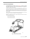
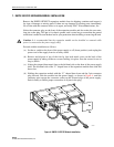
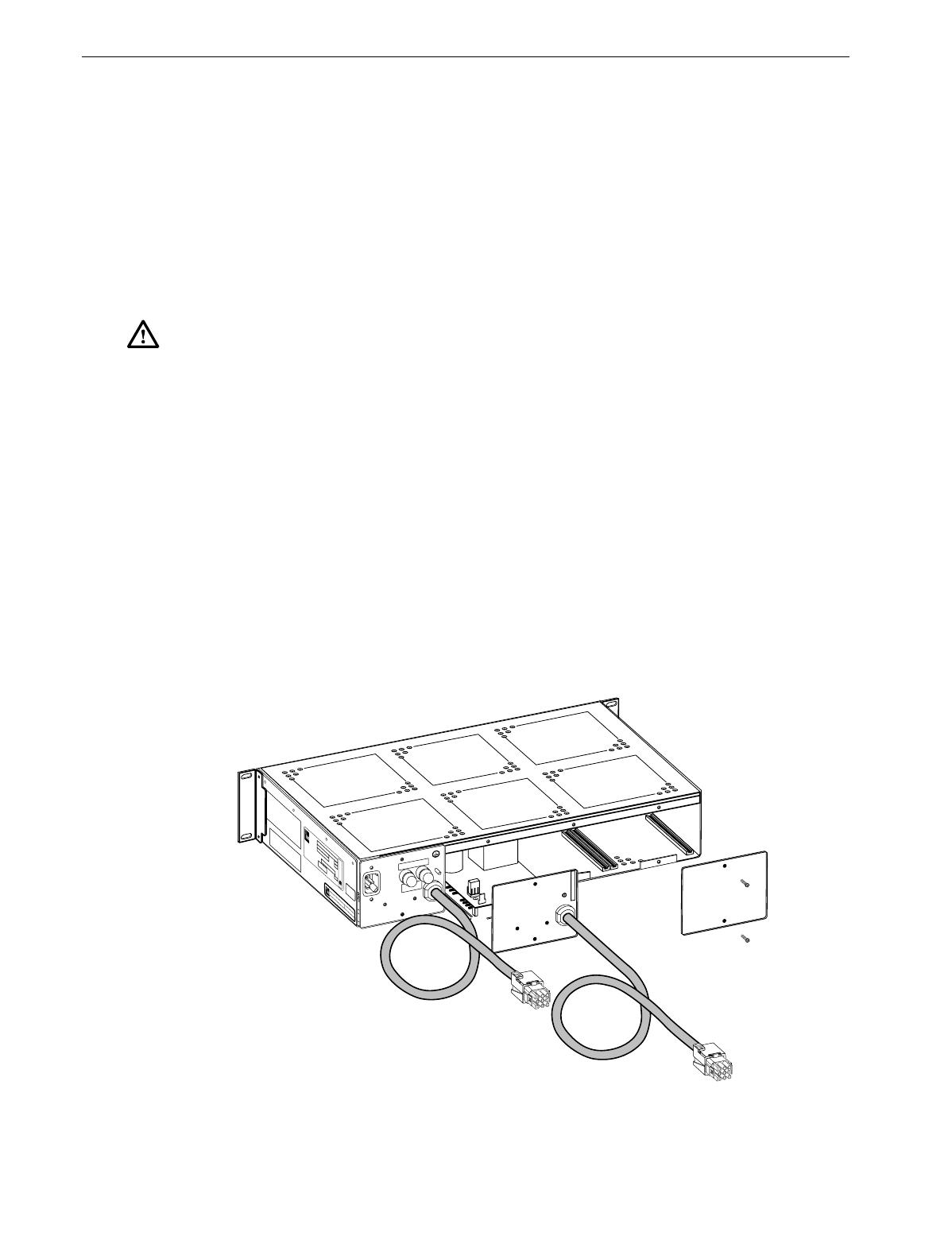
(d)Holding the expansion module with the “U” shaped base down and the 5-pin connector
plug forward, slide the module into the power supply, as shown in Figure 4, until the
connector pins engage the connector socket on the forward edge of the power supply.
Push in firmly to ensure proper connection of all pins in the plug.
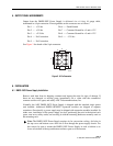
8270-A
CAT #
S/N
DATE
CODE
MADE
IN USA
UR
MODEL
VOLTS
HERTZ
DATE CODE
AMPS
OUTPUT
VOLTS
AMPS
PH
CAUTION
ATTENTION
CAUTION
ATTTENTION
CAUTION: DOUBLE POLE
NEUTRAL FUSING
250V 4A T
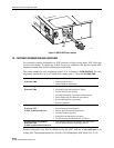
Figure 4. DMPS-10 EXP/CE Module Installation