


PG-Flex Deployment LTPH-UM-1234-01
8 April 30, 2003 HDU-409 Lists 1, 2, and 3
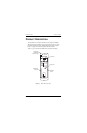
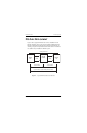
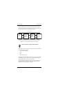
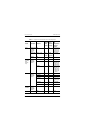
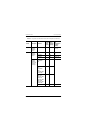
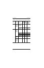
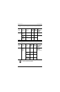
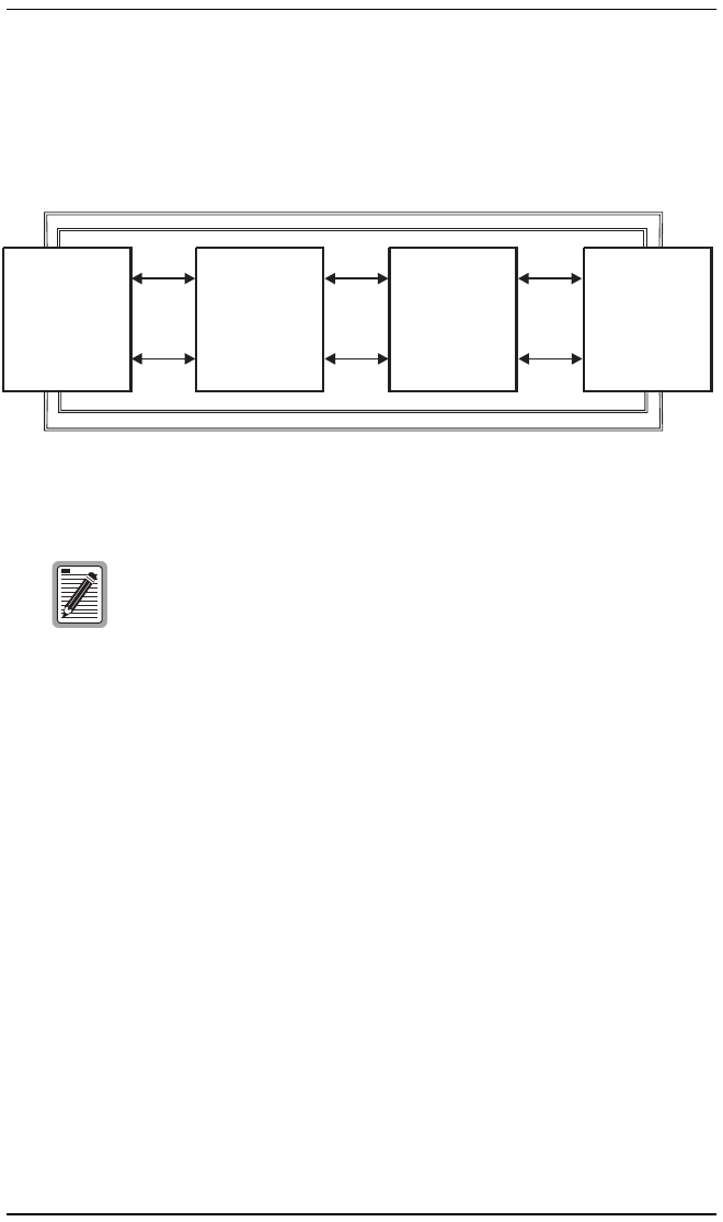
With two doublers, four sets of auxiliary power pairs must be installed
between COT and the RT. These auxiliary power pairs must be the same wire
gauge (or larger) as the pairs used for HDSL and power.
Figure 3. Two Doubler HDU Installation with PG-Flex
The PG-Flex system can operate with a number of other systems, sharing the
same cable binder group, such as:
• T1 (1.544 Mbps capability)
• POTS
• DDS
• Other PG-Flex systems
With doublers, PG-Flex CO line units produce ±125V to ±130V on the HDSL
and auxiliary power pairs. At least ±75V is required at the RT for ringer
voltage and POTS loop current to meet specification.
Refer to the PG-Flex COT shelf, RT enclosure, and line unit practices for
additional information on PG-Flex powering and auxiliary power pair
requirements (see “Documentation” on page iii).
PG-Flex systems do not support doubler loopbacks.
PG-Flex
RT
Doubler 1
HDU-409-L2
HDU-409-L3
PG-Flex
COT
Span 1
HDSL
Auxiliary Power Pairs
Span 2
HDSL
Doubler 2
HDU-409 L2
HDU-409-L3
Span 3
HDSL
H0075-A