ADCP-92-063 • Issue 1 • May 2005
Page 6
© 2005, ADC Telecommunications, Inc.
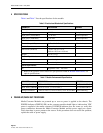
2 UNPACKING AND INSPECTION
Unpack and inspect the module as follows:
1. Inspect the exterior of the shipping container(s) for evidence of rough handling that may
have damaged the components in the container.
2. Unpack module, carefully checking it for damage and verify with the packing slip. If any
item is damaged, consult ADC for repair, replacement, and warranty information. Even
though no damage is evident, save the shipping container for use if the equipment requires
shipment at a future date.
3. File a claim with the commercial carrier and notify ADC Customer Service if damage is
detected or if parts are missing. Save damaged cartons for inspection by the carrier.
4. Refer to Customer Information and Assistance if you need to contact ADC.
5. Save all shipping containers for use if the equipment requires shipment at a future date.
3 INSTALLATION
3.1 1000 Mb/s Module
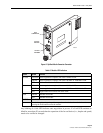
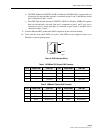
Each 1000 Mb/s module has a 2-position dip-switch for enabling or disabling the UTP
(Unshielded Twisted Pair) Link upon detection of the fiber optic link. Position 1 enables or
disables the UTP link independently of the fiber link. Position 2 reports the configuration to the
CPU through the backplane interface. Position 1 and position 2 must be set to the same positions.
If DIP switches are set to the ON position, then the UTP side follows the fiber side. For
example, if the fiber side links then the UTP side links also. If fiber side is not linked or loses
link, then UTP side is not allowed to link or will drop the link. If switch is configured to the
OFF position, then UTP link does not follow the fiber link. The UTP side links regardless of the
status of the fiber side. Table 3 shows the dip-switch positions.
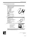
Caution: Electronic modules can be damaged by electrostatic discharge (ESD). To prevent this,
take the following precautions:
• Wear an anti-static-discharge wrist strap while handling modules.
• Place modules in anti-static packing material when transporting or storing them.
• Place modules on an approved, electrically grounded, anti-static mat when working on them.
Table 3. 1000 Mb/s Dip-Switch Positions
DIP SWITCH DESCRIPTION
1 ON = UTP Link dependent of Fiber Link
OFF = UTP Link independent of Fiber Link (Default position)
2 ON = Reports to CPU the UTP Link dependent of Fiber Link
OFF = Reports to CPU the UTP Link independent of Fiber Link (Default position)


