ADCP-92-063 • Issue 1 • May 2005
Page 8
© 2005, ADC Telecommunications, Inc.
5. Verify that the POWER LED is lit.
6. Remove the dust covers from fiber cable ends and from the media converter SFP.
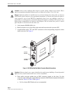
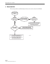
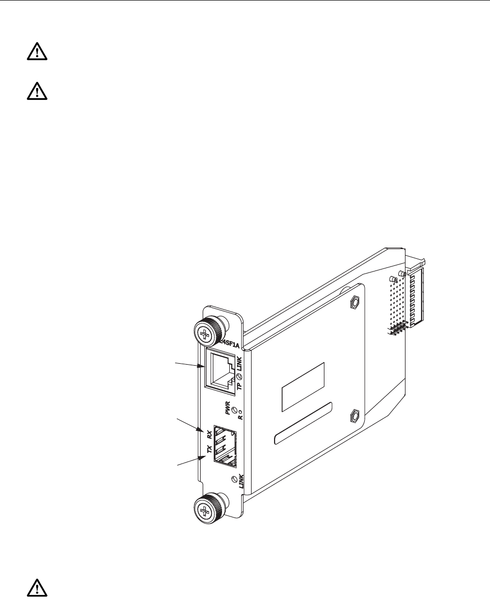
7. Attach the fiber cable “TX” and “RX” connectors to the corresponding receptacles on the
media converter. See Figure 4.
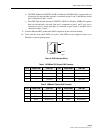
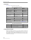
Figure 4. 10/100 Mb/s OptEnet Media Converter Module Connections
8. Each media converter module has an RJ45 connector located on the front. Use this
connector when making the copper Ethernet connection. RJ45 Patchcord pinout information
is shown in
Table 4
or
Table 5
and
Figure 5
.
a. Cat 5e or better RJ45 Patchcords are recommended.
Caution: Always allow sufficient fiber length to permit routing without severe bends. Fibers
may be permanently damaged if bent/curved to a radius of less than 1.5 in. (3.81 cm).
Danger: Infrared radiation is invisible and can seriously damage the retina of the eye. Do not
look into the optical connector of an operational transmitter, or into the end of an active fiber. A
clean, protective cap or hood MUST be immediately placed over any radiating connector or
optical fiber to avoid exposure to potentially dangerous amounts of radiation. This practice also
helps prevent contamination of connectors and adapters. Do not assume laser power is turned
off or the fiber is disconnected at the other end.
Caution: Ethernet signals over copper should not be used between buildings. Ground potential
differences may cause transmission errors or line card failures.
20460-A
RJ45
CONNECTOR
OPTICAL
TRANSMIT
OPTICAL
RECEIVE


