ADCP-80-575 • Issue 2 • December 2006
Page 8
© 2006, ADC Telecommunications, Inc.
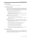
– An alarm can be cleared in any KLM fuse position by installing a new fuse and
removing it when the green LED flashes. When the alarm is cleared, the LED changes
from red to unlit (no red light or green light). The LED remains unlit until a good fuse
in installed, whereupon it turns green. For the alarm clearing procedure, refer to
Section 6.1 on Page 28.
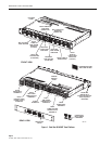
The maximum current capacity of each power bus circuit is 100 Amps. The total output current
capacity of the fuses on each bus must, therefore, not exceed 100 Amps. The maximum current
rating is marked on the fuse platform rear side. The power dissipation of the panel is 80 watts
maximum per fuse platform (40 watts per bus at 100 Amps).
1.8 Bus Capacity
The current capacity of each power bus is 100 Amps maximum, which is marked above the
input connectors on the rear of the fuse platform. The total current of a fuse platform with two
buses is 200 Amps maximum. The power dissipation of the fuse platform is 80 watts maximum
per fuse platform (40 watts per bus at 100 Amps).
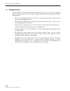
The following lists the maximum current that each type of fuse can provide:
• TPA type fuse (each fuse in four position module): 50 Amps max.
• KLM type fuse (each fuse in two, four, or five position modules): 30 Amps max.
• GMT type fuse (each fuse in four position module): 15 Amps max.
• GMT type fuse (each fuse in 10 position module): 10 Amps max.
1.9 Input Voltage
The fuse platform can accommodate –24 Vdc input power on both busses or –48 Vdc input
power on both busses. The voltage is sensed by the fuse platform circuitry.
The input voltage used with the fuse platform is required to have the following voltage
characteristics:
• –24 Vdc nominal, within a range of –21 Vdc to –30 Vdc
• –48 Vdc nominal, within a range of –42 Vdc to –56 Vdc
1.10 Input Power Connectors
Input power to the power bus is supplied through an input power terminal block located on the
rear side of the fuse platform. Dual bus fuse platforms have a separate input terminal block for
each bus. If two buses are present, the terminal blocks are designated A and B, corresponding to
the two power buses.
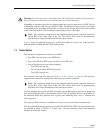
Note: The continuous output load of the equipment during normal operation should not
exceed 80% of the rated value of the fuse. This allows some room for manufacturing
tolerances and voltage fluctuations in the plant power mains.


