ADCP-80-575 • Issue 2 • December 2006
Page 20
© 2006, ADC Telecommunications, Inc.
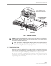
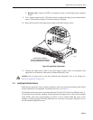
4. Place the fuse platform in the specified mounting space within the rack.
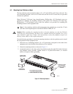
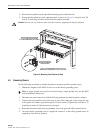
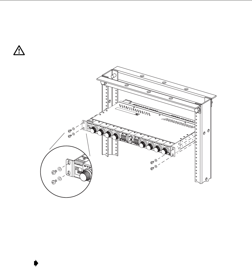
5. Secure the fuse platform to the equipment rack as shown in Figure 14 using the four 3/8-
inch (9.53 mm) long pan-head screws and flat washers provided.
Figure 14. Mounting Fuse Platform on Rack
4.3 Grounding Chassis
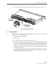
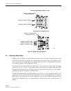
Use the following procedure to connect the panel to an approved office ground source:
1. Obtain two lengths of #10 AWG wire for use as the chassis grounding wires.
2. Terminate one end of each wire with the #10 ring terminals provided (requires crimper).
3. Connect the ring terminal end of each wire to one of the studs and secure using the nuts
with captive star washers provided (requires 3/8-inch socket). Tighten each stud nut to 23
pound-force inches (2.6 Newton meters) of torque.
4. Route the free end of each chassis grounding wire to an approved office ground source.
5. Cut each chassis grounding wire to length and connect it to the office ground source as
required by local code or practice.
Caution: Do not use any hardware other than the hardware supplied with the fuse platform.
Note: A single ground wire can also be used. If using a single ground wire, use #6 AWG
wire terminated at either stud.
18865-A
DETAIL DRAWING OF
MOUNTING SCREWS
AND WASHERS
USE #12 STAR WASHERS INSTEAD OF FLAT
WASHERS IF REQUIRED BY LOCAL PRACTICE
TIGHTEN MOUNTING SCREWS
TO 27 POUND-FORCE INCHES
(3.1 NEWTON METERS) OF TORQUE


