


2
w w w . a d c . c o m • + 1 - 9 5 2 - 9 3 8 - 8 0 8 0 • 1 - 8 0 0 - 3 6 6 - 3 8 9 1
Pro Patch
TM
Optical Normal Through Panel
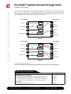
Module Schematics
The new Pro Patch Optical Normal Through Panel provides patch by exception, normal through functionality.
Fiber “Source” and “Destination” connections are located on the rear of the panel, with a normal through
connection between the “Source” and “Destination” ports. To enable patching functionality, a fiber patch
cord is plugged into the front of the panel and a switch is flipped.
9 / 0 6 • 1 0 3 4 4 7 A E
Pro Patch
TM
Optical Normal Through Panel
A Source
A Destination
B Source
B Destination
90%
Monitor
Patched
90%
10%
Monitor
Source
Source
Destination
Destination
Back of Module Front of Module
Switch
90/10 Tap
90/10 Tap
Switch
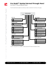
A Source
A Destination
B Source
B Destination
90/10 Tap
90%
10%
Monitor
Normal
Switch
90/10 Tap
90%
10%
Switch
Monitor
Source
Source
Destination
Destination
Back of Module Front of Module
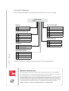
Description Catalog Number
Empty chassis with power supply
3 RU chassis with power supply and IEC cord, patch cord storage in rear
3 RU chassis with power supply and IEC cord, splice tray area in rear
4 RU chassis with power supply and IEC cord, patch cord storage in rear
4 RU chassis with power supply and IEC cord, splice tray area in rear
Power supply
Replacement power supply with IEC cord
PPO-3RU-P
PPO-3RU-S
PPO-4RU-P
PPO-4RU-S
PPO-PWR
O r d e r i n g I n f o r m a t i o n
These are preliminary specifications.
Call an ADC distributor for more details. To find a distributior near you visit adc.com/partners.