


3
w w w . a d c . c o m • + 1 - 9 5 2 - 9 3 8 - 8 0 8 0 • 1 - 8 0 0 - 3 6 6 - 3 8 9 1
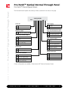
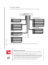
The information below explains the ordering numbers contained in the charts on this page.
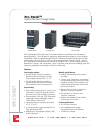
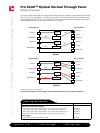
Pro Patch
TM
Optical Normal Through Panel
Pro Patch™ Preconfigured Panels
9 / 0 6 • 1 0 3 4 4 7 A E
Pro Patch
TM
Optical Normal Through Panel
Modules Loaded
1-6 Number of modules loaded
Catalog Number
PPO - __ __ __ __ __ __ __ __ - __
Panel Size
3 3 RU
4 4 RU
Rear Cable Management/splice
0 Patch cord slack storage
2 Heat shrink splice trays
3 Mass Fusion splice trays
Power Supply
0 No cord
1 With IEC cord
Rear Connector/Splice
2 SMFC
7 SMSC
J SMSC (8º angled polish)
8 SMLC (4 RU only)
0 Pigtail for splicing
4 SMST
Monitor Split Style
0 No monitor
A 90/10
B 95/5
C 99/1
Front Patch Connector Style
2 SMFC
7 SMSC
J SMSC (8º angled polish)
8 SMLC (4 RU only)
4 SMST
Switch Type
0 Standard individual
2 Pair switch together
Monitor Port Connector
0 No monitor
F SMFC (8º angled polish)
J SMSC (8º angled polish)
Q SMALC (4 RU only)
Custom configurations are available. Please contact ADC Technical Assistance Center.