


Step 4
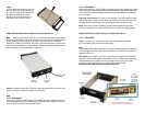
Turn the Diamond enclosure over with
the hard drive mounting holes facing
up. Use the included flat head screws
to secure the hard drive onto the
bottom of the enclosure and turn in
the screw to the “LOCK” position.
Cable Connections When Used as an External Hard Drive
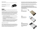
Note: Be sure the Diamond cipher key is inserted into the drive enclosure prior
to turning on the power of the drive enclosure. The hard drive will not be detected
by the computer if the power to the drive enclosure is turned on without the
Cipher key. Under such condition, the power on the drive enclosur will have to be
turned off and turned back on again with the Cipher key already inserted into the
drive enclosure in order to detect the hard drive.
Power: Connect the 6-pin Mini DIN power cable (provided) to the 6-pin Mini DIN
power connector located at the back of the enclosure.
Data:
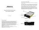
Model: DCHD256ES
Connect the eSATA to eSATA cable to the eSATA connector located at the back
of the enclosure and the other end of the eSATA cable to the eSATA connector
on your SATA host controller with eSATA ports.
Model: DCHD256EU
Connect the eSATA to eSATA cable to the eSATA connector located at the back
of the enclosure and the other end of the eSATA cable to the eSATA connector
on the USB2.0 to eSATA adapter. You can now plug the adapter to a USB port
on your system.
Powering On Enclosure: To power on the enclosure, move the switch located
at the back of the enclosure to the ON mode. When the switch is turned on, the
LED light beside it would light up to indicate power and also drive access.
Note: There are no drivers needed to use the eSATA cable as long as the
drivers are installed for the Serial ATA Controller card/chip. It is plug and play.
Cable Connections When Used as an Internal Hard Drive
Model: DCHD256ES
Power: Use either the 4-pin Molex or the 15-pin SATA power connector.
Do not use both power sources simultaneously.
Data:
Connect the SATA cable to the SATA connector located at the back of the drive
cradle and the other end to the SATA connector on your SATA host controller or
onboard SATA port.
LED cable: Only needed if you want to get drive access signal from the SATA
controller. Use the LED cable to connect the LED pin located at the back of the
cradle (beside the LED switch) to the LED jumper pins on your SATA host
controller or onboard SATA port to enable the drive activity LED.
Factory default, LED signal coming from hard drive.
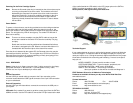
eSATA
connector
On / OFF
switch
Mini-Din power
connector