


Mercury 6-5 M/E Installation guide
Mercury Hub User Guide
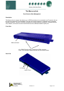
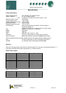
Top View
1
9
0
1
9
0
NETWORK ID
12
3
UPLINK
10BASE-T
Col
Power
Vdc
1 2 3 4 5 6 7 8 9 0
Power
Vac (Option)
100 - 250 Vac
50 - 60Hz
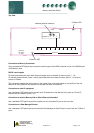
Rs232 Ports
Collision LED
A
ddress selection switches
Power On LED
Connection to Mercury Controllers:
Using a standard CAT5 patch lead, connect the serial output of the RDM Controller to one of the RS232 ports
of the Mercury Hub.
RS232 Lead Lengths
For mains powered hubs, patch lead maximum length must not exceed 15 metres. (ports 1 - 10)
For Mercury powered hubs, inputs 1 and 2 patch leads must not exceed 5 metres, ports 3 - 10 must not
exceed 15 metres.
The 3-character address that will be seen on the system front end is determined by the position of the two
Network ID rotary switches and the port the controller has been connected to.
Connection to other IP equipment
Use a standard CAT5 patch lead to connect other IP equipment to the Mercury Hub (such as a Futura IP
module) into the 10Base T ports 1 or 2.
Connection to another Mercury Hub or Other Ethernet Hub/switch
Use a standard CAT5 patch lead from the Uplink port into a standard IP port on the next Hub.
Connection to a Data Manager/Director
Use a standard CAT5 patch lead and connect the Data Manager or Data Director to one of the two 10 Base T
ports.
Ensure that all power is
switched off before
installing or maintaining
this product
Revision 1.5 Page 4 of 6