


Mercury 6-5 M/E Installation guide
Mercury Hub User Guide
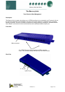
10 Base T connectors
The three 10Base T connectors have 2 leds on them: The green LED; when static, indicates that the
connection to the device is good, the green LED then flickers when data is being transmitted.
The amber LED indicates there is an error or fault on that channel.
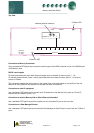
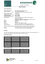
Network ID
The 3-character network ID is made up from the positions of the 2 rotary switches and the RS232 connector
number. We recommend that the 2 rotary switches are set to the Bay number and that the case sections are
plugged into their corresponding RS232 port numbers.
E.g. Bay 10 case 2:
The 2 rotary switches set to "1" and "0", controller plugged into port 2. The ID then is seen as "102" at the
system front end.
1
9
0
1
9
0
NETWORK ID
12
3
Vdc
1 2 3 4 5 6 7 8 9 0
Controller
at position 2
Note that case number 10 would plug into RS232 port 0 (right most port) and come through as "100".
ID for equipment with rotary switch’s.
For RDM products that use the 3 rotary switch’s for the network ID (such as Powertrays), the ID will follow
what is set on the controller local switch’s and NOT the port position on the Hub.
Ensure that all power is
switched off before
installing or maintaining
this product
Revision 1.5 Page 5 of 6