


5Section 61245207L2-5, Issue 261245207L2-5C
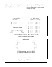
FT1 DP Option Selections
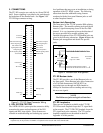
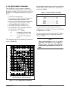
Configuration strap P1, illustrated in Figure 2, selects
FT1 DP settings.
By selecting -190 V, the FT1 DP can power up to two
FT1 repeaters and a locally-powered FNID.
The settings on the FT1 DP are encoded and
transmitted to the FNID once the circuit has achieved
synchronization.
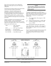
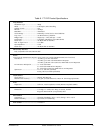
Faceplate Indicators
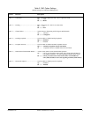
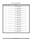
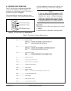
The FT1 DP has six faceplate LEDs which indicate
operational status. Table 4 defines these LEDs.
Table 4. Front Panel Indicators and Switches
Description
Indicates four possible states of the quality of the DSL signal. (The signal quality has a provisionable
threshold of 2, 4, 6, or 8 dB above a 10
-7
BER.)
Off ......................... No synchronization of FT1 DP and FNID
Yellow ................... Poor signal quality (below 2 dB above 10
-7
BER)
Green .................... Good signal quality (above 2 dB above 10
-7
BER)
Blinking ................ An error has been detected on the loop
Indicates four possible conditions:
Green .................... The customer-side DS1 signal is present and synchronized
Yellow ................... Yellow alarm at customer side DS1
Off ......................... No customer-side DS1 signal present
Blinking ................ An error has been detected at FNID input
Indicates three possible loopback states:
Off ......................... No active loopbacks
Blinking ................ FNID or repeater is in loopback
On (solid) ............. Local (FT1 DP) loopback is active
Sealing current is present
Indicate alarm condition
On ......................... Alarm condition detected either locally (FT1 DP) or remotely (FNID)
Off ......................... No alarm condition detected
This LED will be On when Hardware Provisioning does not match software provisioning.
Selects number of DS0 channels. (See subsection 1 of this practice for a description of time slot allocation.)
Indicators
DSL ........................
DS1 .........................
LB ...........................
SX ...........................
ALM .......................
AP ...........................
Rotary Switch.........
Figure 2. P1 Switch Location
P1
o
o
o
P1
o
o
o
-137 V
-190 V