


361291006L2-5B Section 61291006L2, Issue 2
When inserted into a powered up backplane the
TROCU DP and TRDDS-R will synchronize within 30
to 90 seconds. When synchronized, the SYNC LOSS
indicator LED will turn Off. If synchronization cannot
be achieved, check the T/R pair for an open circuit or
short circuit condition, or load coils (see LED
Indicators).
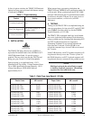
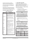
4. TESTING
Testing for the TROCU DP is accomplished using the
same test procedures for four-wire OCU and OCU DP
units. Table 2 describes cable loss for the TRDDS
Nyquist frequency of 13.3 kHz.
The TROCU DP is equipped with logic level bantam
test access jacks that permit testing in both directions
using a portable test set. Latching and alternating OCU
and CSU loopback sequences are supported.
Alternating loopbacks do not operate when the 64
kbps data rate is selected. Choose NEAR to test
toward the customer loop; choose FAR to test toward
the T-carrier.
In the FAR direction, an OCU loopback sequence will
loop the unit directly across the T-carrier system. In
the NEAR direction, an OCU loopback sequence will
loop the unit directly connected to the portable test set.
NOTE
If 64 kbps is selected, the unit will only respond
to latching loopback sequences. Alternating
sequences are not valid at this rate.
elbaCcitsalPtfk/ssoLBdelbaCrepaPtfk/ssoLBd
)F0(CIPeguaG91
)F07(CIPeguaG91
)F021(CIPeguaG91
2035.0
3806.0
0166.0
)F0(PLUPeguaG91
)F07(PLUPeguaG91
)F021(PLUPeguaG91
6165.0
5146.0
5596.0
)F0(CIPeguaG22
)F07(CIPeguaG22
)F021(CIPeguaG22
219.0
8520.1
5101.1
)F0(PLUPeguaG22
)F07(PLUPeguaG22
)F021(PLUPeguaG22
4549.0
6060.1
0731.1
)F0(CIPeguaG42
)F07(CIPeguaG42
)F021(CIPeguaG42
1752.1
2893.1
7194.1
)F0(PLUPeguaG42
)F07(PLUPeguaG42
)F021(PLUPeguaG42
0092.1
4234.1
8625.1
)F0(CIPeguaG62
)F07(CIPeguaG62
)F021(CIPeguaG62
3286.1
8658.1
8179.1
)F0(PLUPeguaG62
)F07(PLUPeguaG62
)F021(PLUPeguaG62
1576.1
9648.1
8069.1
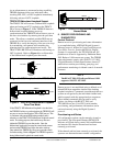
C A U T I O N !
SUBJECT TO ELECTROSTATIC DAMAGE
OR DECREASE IN RELIABILITY.
HANDLING PRECAUTIONS REQUIRED.
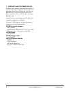
In lieu of option switches, the TROCU DP Preferred
Option has been preprovisioned with feature settings
as indicated in Table 1.
Table 1. Preprovisioning
erutaeFgnitteS
kcabpooLgnihctaLNO
noisserppuSedoCoreZ
dna,CS,spbk65sselnU(NO
)FFO=spbk46
noitcerroCrorrEFFO
3. INSTALLATION
The TROCU DP plugs directly into a WECO or
equivalent D4 channel bank or the ADTRAN ACT
1900/2300 channel bank. No special wiring is
required. The two-wire loop uses the T/R (Tip and
Ring) pair, pins 24 and 51 of the D4 backplane.
Span-powering is accomplished using -130 V,
measured from Tip to Ring. Voltage measured from
Tip to GND should indicate approximately -130 V;
voltage from Ring to GND should indicate
approximately 0.0 V.
Table 2. Cable Type Loss Data @ 13.3 kHz