


561291006L2-5B Section 61291006L2, Issue 2
and manual switch settings by pressing the
momentary Alternate Provisioning (AP) switch
located on the front panel. If the channel unit is
removed from the system, the unit retains previous
provisioning information in nonvolatile Random
Access Memory (RAM).
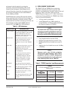
The REM indicator remains ON when the channel
unit is operating based on Remote Provisioning, and
is OFF when operating on manual switches. If the
channel unit has never been remotely provisioned, the
AP switch has no effect and the REM indicator
remains OFF. See Table 3 for LED Indicators.
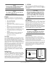
Table 3. LED Indicators
ROTACIDNINOITPIRCSED
SSOLCNYScnysonsierehttahtsetacidniNO
ehtdnaPDUCORTehtneewteb
rofkcehc;R-SDDRTetomer
rehtodna,sliocdaol,ytiunitnoc
.snoitidnocenillamronba
CRCRAENsrorreeraerehttahtsetacidniNO
;maertsatadgnimocniehtno
enillamronbaehtrofkcehc
UCORTehtotresolcsnoitidnoc
.PD
CRCRAFsrorreeraerehttahtsetacidniNO
etomerehtsdrawotgnirrucco
ehtrofkcehc;R-SDDRT
otresolcsnoitidnocenillamronba
.R-SDDRTeht
MERsahtinuehttahtsetacidniNO
;denoisivorpyletomerneeb
ehttahtsetacidniGNIHSALF
.evitcasiknillortnocetomer
elggototnottubPAehthsuP
etomerdnalaunamneewteb
.gninoisivorp
CSIDMQytilauQehttahtsetacidniNO
.derruccosahtcennocsiDrotinoM
USDONehtfoecnesbaehtsetacidniNO
saUSC/USDremotsuc
.R-SDDRTehtybdenimreted
KBLUSCroUCOehtsetacidniNO
.noitavitcakcabpool
ELDIehtfoecneserpehtsetacidniNO
ehtdrawoteldIedoMlortnoC
.krowten
6. DEPLOYMENT GUIDELINES
The TROCU DP and TRDDS-R use technology
designed to eliminate the need for repeaters and
concerns over impairments caused by typical noise and
bridge tap. Table 2 describes cable loss for the
TRDDS Nyquist frequency of 13.3 kHz. Listed below
are the loop design guidelines for TRDDS (See Tables
2 and 4 for more information).
• All loops must be nonloaded.
• Actual Measured Loss (AML) should not
exceed 50 dB at 13.3 kHz (135 Ω termination),
the Nyquist frequency of TRDDS.
NOTE
The 50 dB AML limit includes 6 dB of signal
margin to account for potential near-end cross
talk (NEXT) from other digital services that
may be provisioned in the same binder group.
• Loop length should not exceed 50 kft.
• Bridged tap length should not exceed 12 kft.
• Background noise level should not exceed 34
dBrn.
• Impulse noise level should not exceed -40 dBm,
(+50 dBrn).
NOTE
Measure noise with 50 kbit weighting
characteristic approximating a filter with a
passband of 40 Hz to 30 kHz. Background
noise level or impulse noise level is referenced
from 56/64 kbps data rate in TR62310.
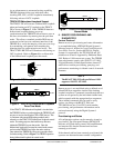
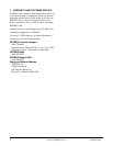
Table 4. TRDDS Insertion Loss Measurements
SDDRT
lanoitidartrofzHk82otderapmoczHk3.31
ecivresSDD
eniL
noitarugifnoCnoitarugifnoC
noitarugifnoC
noitarugifnoCnoitarugifnoC
zHk3.31@zHk82@
GWA62tfk72Bd21.05Bd53.56
GWA42tfk52.63Bd00.05Bd05.26
GWA22tfk05Bd42.05Bd33.95