


Section 61102040L4-5, Issue 261102040L4-5B
3
C A U T I O N
C A U T I O N
!
SUBJECT TO ELECTROSTATIC DAMAGE
OR DECREASE IN RELIABILITY.
HANDLING PRECAUTIONS REQUIRED.
The U-BR1TE III will function with any ISDN 2B1Q
U-interface that is ANSI T1.601 compliant.
2. INSTALLATION
After unpacking the unit, inspect it for damage. If
damage is noted, file a claim with the carrier, then
contact ADTRAN. See Warranty and Customer
Service.
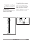
To install the U-BR1TE III, hold the unit by the front
panel and insert it into the assigned slot until the edge
connector is firmly seated in the backplane. The ACT
LED on the U-BR1TE III should illuminate GREEN.
The CR and LP LEDs will flash GREEN then
illuminate AMBER. At this point, push the unit latch
upward until it locks into place.
NOTE
During installation rotary switch SW3 can be in
any position except 7 (LPBK). LPBK is reserved
for special testing functions.
SLC-5
The U-BR1TE III plugs into a single SLC-5 channel
slot. Because two time slots are assigned to each
physical slot in a SLC-5 channel bank, and a U-BR1TE
III provisioned as 2B+D requires three time slots,
there are restrictions that apply to the physical
placement of the U-BR1TE III in the channel bank.
Each SLC-5 digroup consists of 12 physical slots,
which can be divided into four groups of three slots
each (physical slots 1-3, 4-6, 7-9, and 10-12). These
tri-slot groups are used to define the slot restrictions
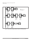
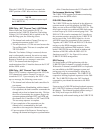
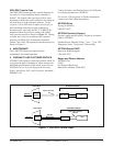
for the U-BR1TE III as follows (see Figure 2):
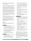
• A U-BR1TE III provisioned as 2B+D cannot be
installed in the last slot of a tri-slot group (slots
3, 6, 9, or 12).
• A U-BR1TE III provisioned as anything other
than 2B+D cannot be installed in the physical
slot to the immediate right of a U-BR1TE III
provisioned as 2B+D within a tri-slot group.
SLC 2000
The U-BR1TE III operates in all SLC-2000 COT and
RT shelves and can be used in combination with any
mix of other SLC-2000 channel units. Currently, the
unit will not operate in a mode 2 shelf. All option
information for SLC-2000 channel units is entered
using the SLC-2000 Craft Interface Terminal (CIT)
and stored in the controller’s nonvolatile system
memory. Once a slot is provisioned, it does not need
to be provisioned again unless a different channel unit
is installed in that slot.
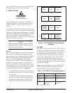
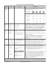
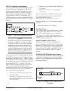
Table 1 lists the options to set for the U-BR1TE III.
The service provisioned should match the switch
settings or the unit may not operate properly.
Figure 2. SLC-5 U-BR1TE Slot Placement
Examples
1B+D
or
2B
1B+D
or
2B
2B+DI
II
III
IV
2B+D Empty
312
645
978
1210 11
2B+D
Available
for Other
Services
2B+D
Empty
Empty
Available
for Other
Services
Available
for Other
Services
Table 1. SLC-2000 CIT Provisioning Options
BRI = Basic Rate Interface
noitpOTOC0002-CLSTR0002-CLS
IELCEJ1CS5EH1CS5
noitcnuF
edoC
IRBIRB
ecivreS,D+1B,D+B2
D,D+2B
,D+1B,D+B2
D,D+2B