


Section 61102040L4-5, Issue 2 61102040L4-5B
8
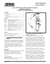
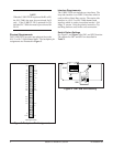
Front Panel Features
The RJ-45 jack allows front panel test access for local
or downstream loopbacks. The address select knob
(SW3) determines which element is being looped
back. Table 3 lists the loopback options.
Three LEDs on the front panel of the U-BR1TE III
report the synchronization and loopback status.
Descriptions of these LEDs are given in Table 4. The
SLC Series 5 COT must be externally timed from a
suitable composite clock with stratum one traceability.
3. TESTING
The U-BR1TE III responds to embedded operation
channel loopbacks, including B1, B2, and 2B+D,
when configured for D channel operations.
When used in B1 configuration (non-D channel modes
of operation) the U-BR1TE III will respond to an in-
band DS0 DP latching loopback sequence. When
remote testing is not available, or during
troubleshooting, the U-BR1TE III front panel provides
local test capabilities for use with industry standard
Digital Logic Test Sets such as the TPI 108/109 or
equivalent testers. Available tests include a local
loopback, loopback of up to 5 addressable
downstream ISDN devices, loopback of the
customer’s NT1, and point-to-point testing in both the
upstream and downstream directions.
NOTE
When a U-BR1TE III is performing a loopback,
the loopback occurs internal to the U-interface
transceiver.
Loopback Tests
Loopbacks in the network-to-customer direction can
be initiated from either the ISDN switch or the front
panel. Front panel initiated loopbacks are non-
obtrusive to unused channels, thereby preventing
synchronization loss or dropouts on the carrier or loop
while testing.
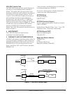
From the RJ-45 jack on the front panel, a DS0 digital
test set is used to inject the required 64 kbps test
pattern into the B1 or B2 channel. The address select
knob determines the downstream element to be looped
back, and the direction of rotation of the knob selects
which channel is to be looped back. Clockwise (CW)
rotation selects the B1 channel, and counterclockwise
(CCW) rotation selects the B2 channel. To initiate a
loopback, perform the following procedure:
1. Connect the DS0 tester to the RJ-45 jack.
2. Rotate the address select knob in the direction
associated with the desired loopback channel
until the desired downstream element address is
reached (see Table 3). The LEDs indicate
successful loopback activation according to Table
4.
3. Data is looped back at the selected address until
the jack is disconnected or the address select
knob is changed.
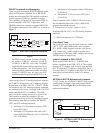
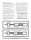
Point-To-Point Test (CRTX/LPTX)
Point-to-point testing using a DS0 digital tester can be
performed to either the T1 carrier interface (SW3,
position 8), or the U-interface (SW3, position 9).
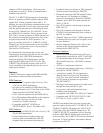
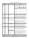
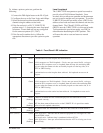
Table 3. Rotary Switch Legend
yalpsiDemaNnoitaterpretnI
01TN1TNehtfosserdda,1TN
.edomSDDniUCOgnihctal
11RDAtinusihtfosserdda,1#sserddA
*22RDAmaertsnwodtxeneht,2#sserddA
yawatinu
33RDAtinudnoceseht,3#sserddA
maertsnwod
44RDAtinudrihteht,4#sserddA
maertsnwod
55RDAtinuhtruofeht,5#sserddA
maertsnwod
66RDAtinuhtfifeht,6#sserddA
maertsnwod
**7KBPLottinusihtsecrof,kcabpooL
2Bro1Bdetcelesehtkcabpool
htobniruccoskcabpooL.lennahc
krowtendnaremotsuceht
.snoitcerid
8XTRCreirracehtni,timsnartreirraC
noitcerid
9XTPLpoolehtni,timsnartpooL
noitcerid
.lennahc1BehtstcelesnoitatoresiwkcolC
lennahc2BehtstcelesnoitatoresiwkcolcretnuoC
gnitteStluafeDyrotcaF*
gnitsetlaicepsrofdevreseR**