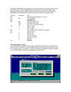
BASE+0 Receiver buffer register when DLAB=0 and the operation is a read.
BASE+0 Transmitter holding register when DLAB=0 and the operation is a write.
BASE+0 Divisor latch bits 0 - 7 when DLAB=1
BASE+1 Divisor latch bits 8-15 when DLAB=1.
The two bytes BASE+0 and BASE+1 together form a 16-bit number, the divisor, which
determines the baud rate. Set the divisor as follows:
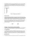
Baud rate Divisor Baud rate Divisor
50 2304 2400 48
75 1536 3600 32
110 1047 4800 24
133.5 857 7200 16
150 768 9600 12
300 384 19200 6
600 192 38400 3
1200 96 56000 2
1800 64 115200 1
2000 58
BASE+1 Interrupt Status Register (ISR) when DLAB=0
bit 0 Enable received-data-available interrupt
bit 1 Enable transmitter-holding-register-empty interrupt
bit 2 Enable receiver-line-status interrupt
bit 3 Enable modem-status interrupt
BASE+2 FIFO Control Register (FCR)
bit 0 Enable transmit and receive FIFOs
bit 1 Clear contents of receive FIFO
bit 2 Clear contents of transmit FIFO
bits 6-7 Set trigger level for receiver FIFO interrupt
Bit 7 Bit 6 FIFO trigger level
0 0 01
0 1 04
1 0 08
1 1 14
BASE+3 Line Control Register (LCR)
bit 0 Word length select bit 0
bit 1 Word length select bit 1
Bit 1 Bit 0 Word length (bits)
0 0 5
0 1 6
1 0 7
1 1 8
bit 2 Number of stop bits
bit 3 Parity enable
bit 4 Even parity select
bit 5 Stick parity
bit 6 Set break
bit 7 Divisor Latch Access Bit (DLAB)


