


ix
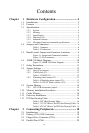
Contents
Chapter 1 Hardware Configuration.................................2
1.1 Introduction....................................................................... 2
1.2 Features ............................................................................. 3
1.3 Specifications.................................................................... 3
1.3.1 System.............................................................................3
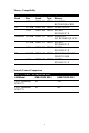
1.3.2 Memory........................................................................... 4
1.3.3 Input/Output.................................................................... 4
1.3.4 Ethernet LAN..................................................................5
1.3.5 Industrial features ...........................................................5
1.3.6 Mechanical and environmental specifications................ 5
1.4 Jumpers and Connectors.................................................... 6
Table 1.1:Jumpers........................................................... 6
Table 1.2:Connectors......................................................6
1.5 Board Layout: Jumper and Connector Locations..............8
Figure 1.1:Jumper and Connector locations...................8
Figure 1.2:I/O Connectors..............................................9
1.6 AIMB-760 Block Diagram.............................................. 10
Figure 1.3:AIMB-760 Block Diagram..........................10
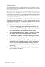
1.7 Safety Precautions.......................................................... 11
1.8 Jumper Settings............................................................... 12
1.8.1 How to set jumpers.......................................................12
1.8.2 CMOS clear (J1)........................................................... 12
Table 1.3:CMOS (J1).................................................... 12
1.8.3 Watchdog timer output (J2).......................................... 13
Table 1.4:Watchdog timer output (J2)..........................13
Table 1.5:ATX/AT Mode selector (J12).......................13
1.9 System Memory .............................................................. 14
1.9.1 CPU FSB and memory speed .......................................14
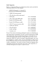
1.10 Memory Installation Procedures ..................................... 14
1.11 Cache Memory................................................................ 14
1.12 Processor Installation ...................................................... 15
1.13 PCI Bus Routing Table ................................................... 16
Table 1.6:PCI Bus Routing Table.................................16
Table 1.7:1U PCI Riser Card PCI Bus Routing Table .16
Table 1.8:2U PCI Riser Card PCI Bus Routing Table .16
Chapter 2 Connecting Peripherals .................................18
2.1 Introduction..................................................................... 18
2.2 Primary (CN1) IDE Connector ....................................... 18
2.3 Floppy Drive Connector (CN3)....................................... 19
2.4 Parallel Port (CN4).......................................................... 20