


EKI-2525M & 2526M User Manual-V2.1-051507 8
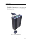
Chapter 2 Installation
In this chapter, you will be given an overview of the EKI-2525M/2526M hardware
installation procedures.
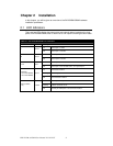
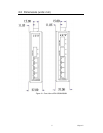
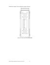
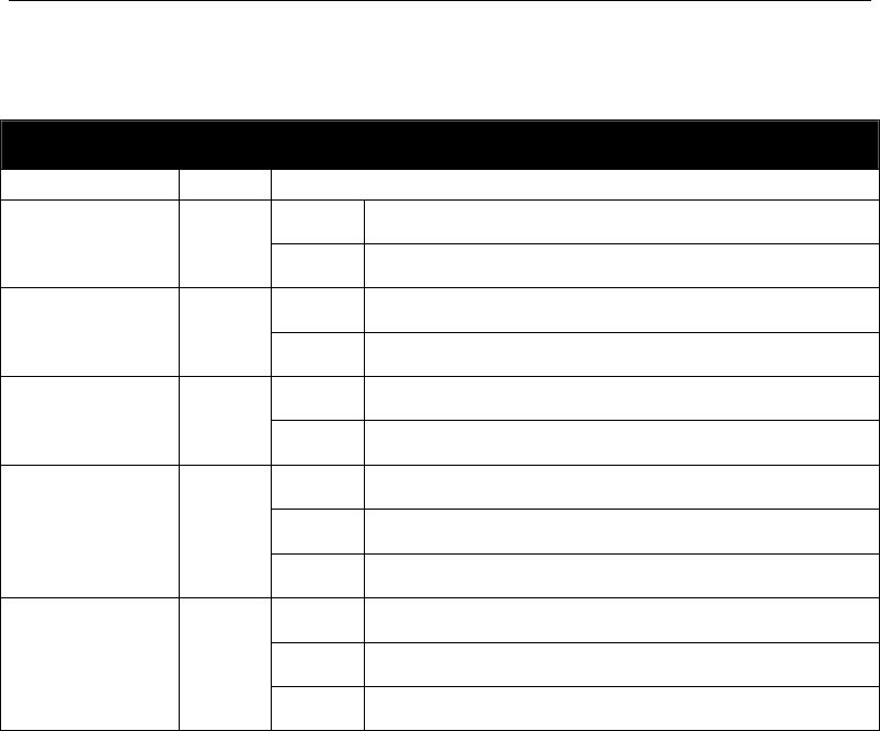
2.1 LED Indicators
There are few LEDs display the power status and network status located on the front
panel of EKI-2525M/2526M, each of them has its own specific meaning as below table.
Table 2.1: EKI-2525M/2526M LED Definition
LED
Color Description
On Power input 1 is active
P1 Green
Off Power input 1 is inactive
On Power input 2 is active
P2 Green
Off Power input 2 is inactive
On Power input 1 or 2 is inactive
P-Fail Red
Off Power input 1 and 2 are both active, or no power input
On Connected to network
Flashing Networking is active
Link/Active
(1~5 for EKI-2525M)
(1~6 for EKI-2526M)
Green
Off Not connected to network
On Ethernet port full duplex
Flashing Collision of packets occurs
Duplex/Collision
(1~4)
Yellow
Off Ethernet port half duplex or not connect to network