


vii Contents
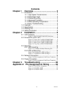
Contents
Chapter 1 Overview ........................................... 2
1.1
Introduction ........................................................ 2
1.1.1
High-Speed Transmissions ....................... 2
1.1.2
Dual Power Input ...................................... 2
1.1.3
Flexible Mounting...................................... 2
1.1.4
Advanced Protection................................. 2
1.1.5
Wide Operating Temperature.................... 2
1.1.6
Easy Troubleshooting ............................... 2
1.2
Features............................................................. 3
1.3
Specification ...................................................... 4
1.4
Packing List ....................................................... 6
1.5
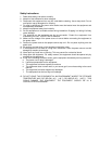
Safety Precaution............................................... 6
Chapter 2 Installation ........................................ 8
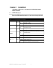
2.1
LED Indicators ................................................... 8
Table 2.1: EKI-2525M/2526M LED Definition........... 8
2.2
Dimensions (units: mm) ..................................... 9
Figure 2.1: Front View of EKI-2525M/2526M............ 9
Figure 2.2: Side View of EKI-2525M/2526M ............10
Figure 2.3: Rear View of EKI-2525M/2526M............11
Figure 2.4: Top View of EKI-2525M/2526M.............12
2.3
Mounting .......................................................... 13
2.3.1
Wall mounting ......................................... 13
Figure 2.5: Combine the Metal Mounting Kit.............13
2.3.2
DIN-rail Mounting.................................... 14
Figure 2.6: Installation to DIN-rail Step 1 ..................14
Figure 2.7: Installation to DIN-rail Step 2 ..................15
2.4
Network Connection......................................... 16
Figure 2.8: Pin Assignment of the Power Connector ..16
2.5
Power Connection............................................ 17
Figure 2.9: Pin Assignment of the Power Connector ..17
Chapter 3 Troubleshooting ............................ 20
Appendix A Pin Assignment & Wiring ........... 22
Figure A.1: RJ-45 Pin Assignment.............................22
Figure A.2: EIA/TIA-568B ........................................22
Figure A.2: EIA/TIA-568A........................................22