


Your ePlatform Partner
User’s Manual for Advantech SOM-A2558 series module V1.00
13
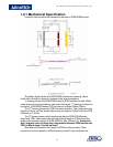
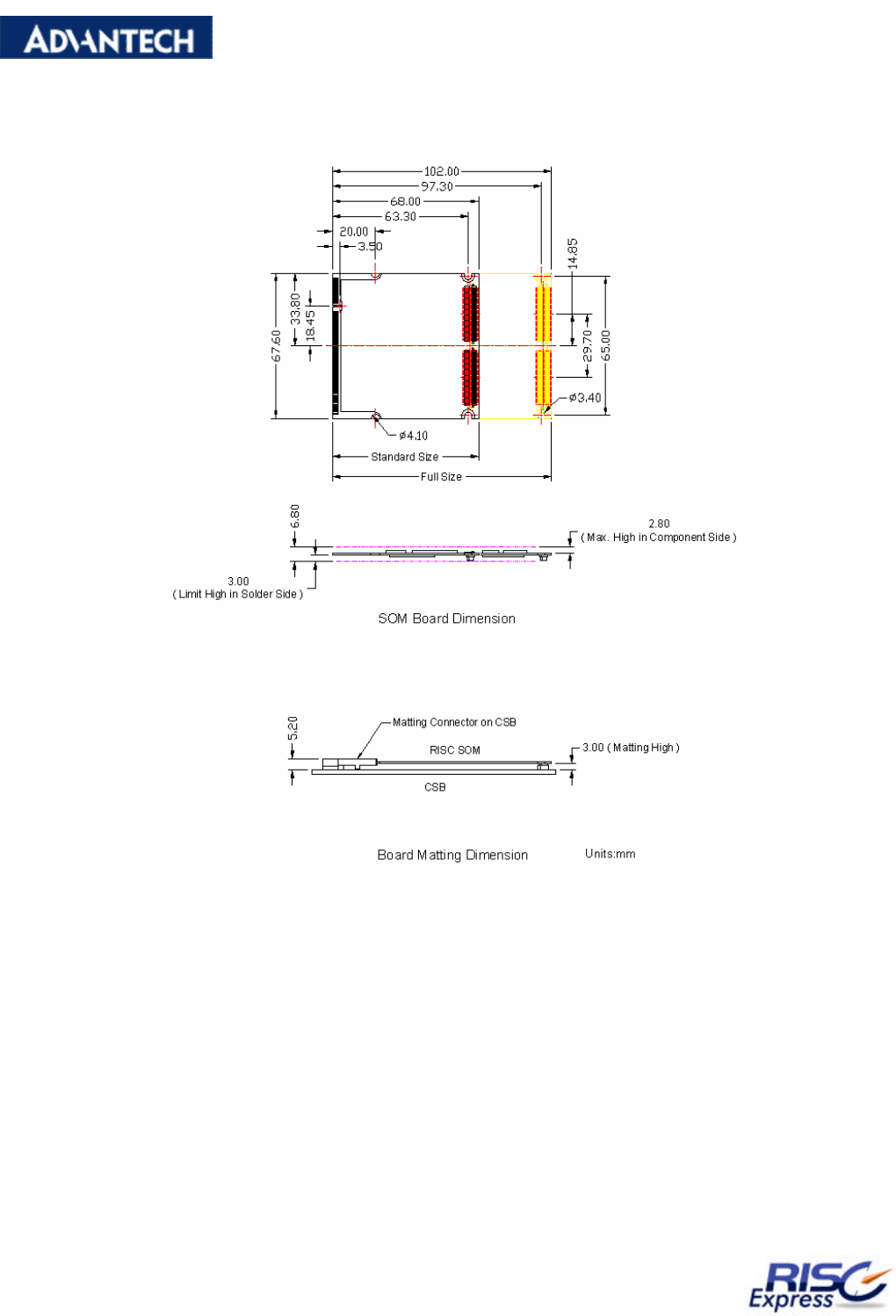
1.2.1 Mechanical Specification
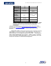
Following figure shows the mechanical drawing of SOM-A2558 series.
The above figure shows the SOM-A2558 mechanical drawing. Users
could follow the above figure to implement the layout procedure.
1
st
drawing shows the SOM-A2558 module PCB mechanical data. When
users enter the layout procedure, user could follow the 1
st
drawing to place the
connector. SOM-A2558 series PCB form factor is 68mm*68mm*68mm.
The 2
nd
drawing shows the PCB thickness limitation. The component side
height is 2.8mm, and the solder side maximum height is 3.00mm and the PCB
thickness is 1.00mm.
The 3
rd
drawing shows allied mechanical data of SOM-A2558 series
board and CSB. Users could see that the matting height is 3.00mm and the
solder side maximum height of SOM-A2558 is also 3.00mm. So, Advantech
don’t suggest users to place any components between SOM module and
CSB in layout stage. It could be short!
Most users will question the height of SOM structure product. Does
product be too thick based on SOM structure product? User could see the