


Your ePlatform Partner
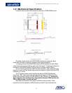
User’s Manual for Advantech SOM-A2558 series module V1.00
21
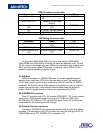
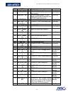
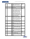
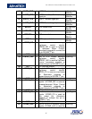
88 PWR_EN
O
Power Enable for the power
supply. (output) When negated, it
signals the power supply to
remove power to the core because
the system is entering sleep mode.
Pull high with
100Kohm
89 BAT_VCC P 3.0V li-
ion coin battery positive
pole input pin.
No pulling
90 nRESET I System hardware reset input pin.
Falling edge triggered. Hard reset.
(input) Level sensitive input used
to start the processor from a known
address. Assertion causes the
current instruction to terminate
abnormally and causes a reset.
When nRESET is driven high, the
processor starts execution from
address 0. nRESET must remain
low until the power supply is stable
and the internal 3.6864 MHz
oscillator has stabilized.
Pull high with
10Kohm
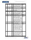
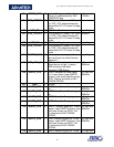
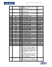
91 nDC_IN I System DC input indicator pin.
When the pin is low, it means
system is powered by external DC
power source. If user target
device
is not power by battery, use could
use this pin as GPIO. The pin
connects to SoC PXA255 GPIO16.
Pull low with
1Kohm
92 SYS_VCC P SOM system DC power 5V input
pin. SYS_VCC should always be
powered by DC 5V even in sleep
mode.
-
93 SYS_VCC3P3
P SOM system DC power 3.3V input
pin. SYS_VCC should always be
powered by DC 3.3V even in sleep
mode.
-
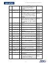
94 SYS_VCC P SOM system DC power 5V input
pin. SYS_VCC should always be
powered by DC 5V even in sleep
mode.
-
95 SYS_VCC3P3
P SOM system DC power 3.3V input
pin. SYS_VCC should always be
powered by DC 3.3V even in sleep
mode.
-
96 SMBUS_CLK
IO
System Management Bus clock
pin. The pin is implemented by
SoC PXA255 I2C bus.
Pull high with
4.7Kohm
97 SYS_VCC3P3
P SOM system DC power 3.3V input
pin. SYS_VCC should always be
powered by DC 3.3V even in sleep
mode.
-