


52
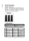
The actively redundant parallel operation automatically
switches to power-increasing operation if the output power
requirement exceeds the UPS single block power, i.e. the
degree of redundancy is decreased or is completely eliminated.
Conversely, the active UPS redundancy degree automatically
increases again when the power consumption decreases.
The connection normally takes place in the low-voltage main
distribution, which also contains the external manual bypass
and the following subdistribution of connected load circuits.
Such a parallel board can be purchased in a wall housing incl.
external HU as well as feeder and load distribution board from
AEG Power Solutions via your specialist dealer.
9.2 Set-up / Connection of Parallel Operation Board
The mains connection of each individual UPS takes place in
the same way as described in chapter 5.
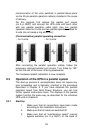
The three-phase mains connection secured for
each UPS must always have the same phase
sequence, i.e. all UPS units are supplied at the
input terminals L1, L2 and L3 by the same
phase each time (no mix!).
In UPS bypass mode, the phase L1 is used to
connect the single-phase load with the mains.
The central external manual bypass, which must
have an all-pole design, must also be supplied
by this phase L1.
The UPS outputs are each connected with the parallel
operation busbar via an isolator. The instructions from
chapter 5 apply here too.
The following always holds true for the UPS input and output
conductors: The difference in length in conductors up to 20 m
per UPS can be max. 20% and max. 10% for lengths > 20 m
per UPS.
The jumper installed between “JP1” and “JP2” on the
connection panel of every UPS at the factory must be
removed. The UPS output distribution also has to take place
according to the instructions in chapter 5. In particular, make
sure that the individual switching elements are correctly
labelled, in order to prevent operating errors later as well. The