


Thermo Scientific Agilent 1100 Series LC Devices Connecting the Hardware and Triggering Data Acquisition 3
2
Connecting the Hardware
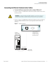
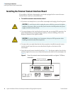
This chapter describes how to install the interface boards, connect the Ethernet cables, and
make the contact closure connections required to control an LC/MS system (Agilent
LC/Thermo scientific MS) system from Xcalibur.
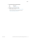
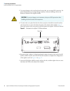
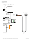
Ethernet Communication Kit
To connect an Agilent 1100 series HPLC to your Thermo Scientific MS detector, you must
have the Ethernet Communication kit (P/N OPTON 30012), which contains the parts listed
in Tabl e 2. In addition, one of the modules of the Agilent 1100 Series LC must have a
JetDirect 400N LAN card (P/N 00825-01140) or an Agilent LAN interface board, model
number G1369A.
Contents
• Ethernet Communication Kit
• Installing a Network Card in an Agilent Module
• Connecting the Ethernet Communication Cables
• Installing the External Contact Interface Board
• Connecting the Trigger Cable
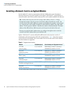
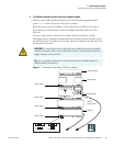
Table 2. Ethernet Communication kit (P/N OPTON 30012)
Description Part Number
Ethernet switch 00825-01-00024
PCB, contact closure, external contact interface 00012-27714
Cable, trigger external contact, 2-wire DB15 00012-27716
Cable, patch, 3 m (10 ft) CAT5 RJ45, straight shield 00012-70008