


2
Connecting the Hardware
Installing the External Contact Interface Board
8 Agilent 1100 Series LC Devices Connecting the Hardware and Triggering Data Acquisition Thermo Scientific
Installing the External Contact Interface Board
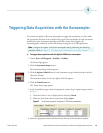
If your Agilent 1100 Series Autosampler is not already equipped with an external contact
interface board, install one as described below.
Y To install the external contact interface board
1. If you have not already done so, turn off the autosampler and unplug it from line power.
2. To prevent damage to the interface board, ensure that you are using ESD protection. For
more information on preventing damage caused by an electric discharge, refer to the
Reference Manual for the Agilent module.
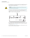
3. To remove the cover plate from the slot where you plan to install the external contact
interface board, loosen the two screws that fasten the plate to the chassis of the
autosampler.
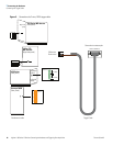
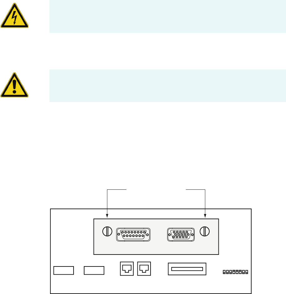
4. Insert the external contact interface board (see Tab le 2 for the part number) into the slot,
and then tighten the two screws to fasten the board to the chassis of the autosampler. See
Figure 4.
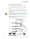
Figure 4. View of the external contact interface board installed in an Agilent 1100 Series
autosampler
CAUTION To avoid electric shock, unplug the power cable that connects the Agilent
module to line power. After you turn the power switch to the Off position, the power
supply continues to draw current.
CAUTION To prevent damage to an instrument, always use ESD protection when
handling electronic boards and components.
1 8
Screws for fastening
the external contact interface board
CAN CAN HP-1B CONFIG
RELAY CONTACTS
REMOTE RS232
VIAL- # -OUTPUT