


3
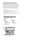
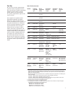
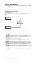
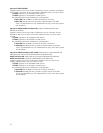
Figure 1. Device characterization
DUT
Processor/Display
Receiver/Detector
Signal separation
Source
Incident
Reflected
Transmitted
Incident
Reflected Transmitted
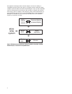
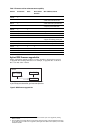
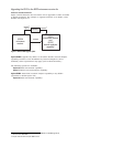
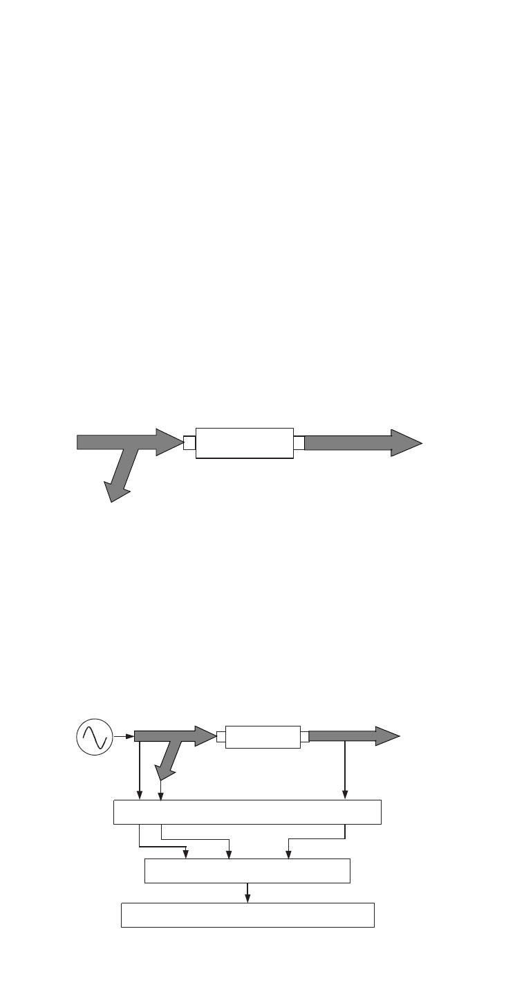
Figure 2. Network analyzer configuration
Vector network analyzer (VNA) overview
Vector network analyzer (VNA) measurement systems are used to fully
characterize the linear behavior of two port devices or networks. Device
characteristics include the magnitude and phase data of the transmission or
reflection parameters that are required to determine complex impedance, both
resistive and reactive components, shown in Figure 1. A network’s behavior is
linear when (1) a linear change in the input results in a linear change in the
output, and (2) the output, resulting from multiple input signals, is the same
as the sum of the outputs resulting from independent input signals. Some
examples of linear networks are filters, amplifiers, cables and isolators.
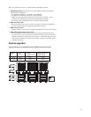
A network analyzer measurement system can be divided into four major parts
shown in Figure 2:
1. A signal source providing the incident signal
2. Signal separation devices to separate the incident, reflected and trans-
mitted signals, and then down converts the microwave signals to a lower
intermediate (IF) signal
3. A receiver to attain the IF signal and down convert it to DC
4. A signal processor and display section that processes the data and displays
information on a CRT
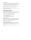
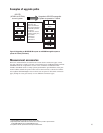
DUT
Transmitted
Incident
Reflected
Reflection
(Reflected/incident):
Input SWR
Return loss
Input/output impedance
Reflection coefficient
S-Parameters S
11
, S
22
Transmission
(Transmitted/incident):
Gain/loss
Isolation
Insertion phase
Group delay
S-Parameters S
21
, S
12