


3
• LED Indicators
Comprehensive LED indicators display the status of the switch and
the network (see Section 1.2.3).
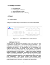
1.2.2 Rear Panel
Figure 1-2 Rear Panel view of the Switch
• Power Adapter Connector: DC 48V/1.5A, AC 100~240V,
50~60Hz
• DC Terminal: used for connection to auxiliary backup DC power,
DC 48V/1.5A
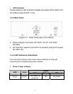
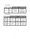
1.2.3 LED indicators information
The front panel LEDs provide instant status feedback for help with
monitoring and troubleshooting when needed.
• Power: Power Indicator
Status
LED Color
Solid Blinking Off
Power Green
The Switch is
power-on
N/A No power