


6 Installing the Hardware June 2007
4 Carefully remove any foam pads and protective plastic
from the switch chassis.
Note. Alcatel-Lucent provides factory-installed blank
cover plates for empty backup power supply or 10-Giga-
bit expansion module bays. Do not remove these cover
plates unless a backup power supply or expansion module
is to be installed immediately at the corresponding bay.
5 If you are installing multiple switches in a stacked
configuration, repeat steps 1 through 4 for the remaining
switches that will make up the stack.
6 Once all OmniSwitch 6850 Series switches have been
removed from their packaging, continue to “Setting Up
the Switch.”
Setting Up the Switch
Note. Due to their airflow and access requirements,
OmniSwitch 6850 Series switches cannot be wall-
mounted.
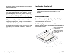
Airflow Considerations
Be sure that your switch is placed in a well-ventilated, static-
free environment. Always allow adequate clearance at the
front, rear, and sides of the switch.
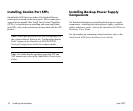
The following diagram shows recommended minimum clear-
ances for adequate chassis airflow and access to components at
the rear of the chassis:
OmniSwitch 6850-48
USB
CLASS 1 LASER PR
ODUCT
OK
1
2
3
4
PRI
PWR
BPS
1 2 3
4 5 6
7 8
9 10 11
12 13
14 15 16
17 18 19
20 21 22
23 24
25 26
27 28 29
30 31 32 33 34
35 36
37 38 39
40 41
42 43 44
45 46 47
48
Rear. 5 inches minimum
at rear of chassis.
Front. 6 inches minimum
at front of chassis for
cable access and LED
visibility.
Sides. 2 inches minimum
at left and right sides for
chassis airflow.
Chassis Top View