


10 505942
Installation
© Copyright, Alliance Laundry Systems LLC – DO NOT COPY or TRANSMIT
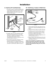
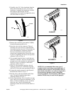
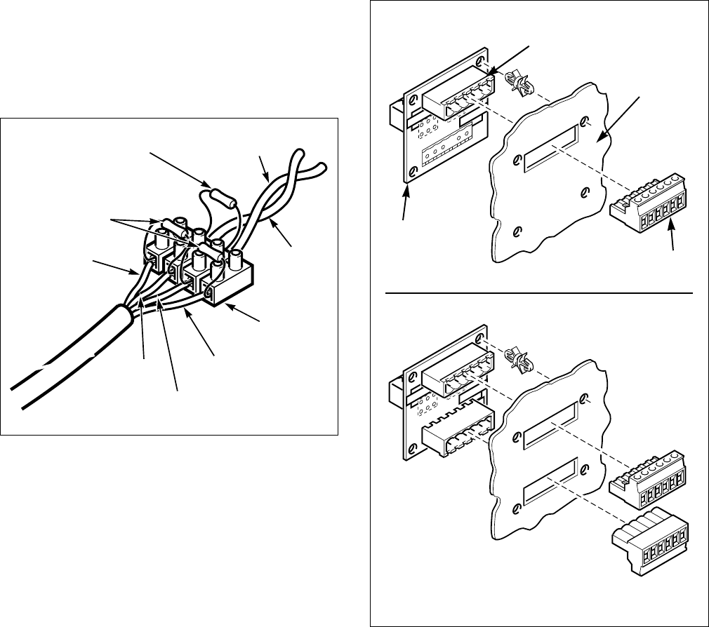
5. Run the wires of the network cable into the
different circuits of the terminal strip and hold
them in place while tightening the screws on
top of the strip. Refer to Figure 3.
6. Carefully strip 1/4" of the insulation from the
black and red twisted pair wire. If too little
insulation is stipped, and insulation is inside the
connector, the network will not communicate.
If too much is stripped, the wires will short.
Refer to Figure 5.
7. Place the black and red twisted pair wire into
the terminal strip and hold the wires in place
while tightening the screw on top of the
terminal strip (connect black wire to black wire
and red wire to red wire). Refer to Figure 3.
NOTE: The 120
Ω 1/2 Watt terminating resistor
connects between the red and black wires of the
twisted pair network wiring.
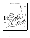
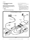
C. Connecting the Machines to the
PC and Each Other
(For up to 124 machines or 4,000 feet of
network length)
1. Run the black/red twisted pair wire to the first
machine to be connected. Follow whatever
sequence is most convenient for store layout.
Be sure you have DISCONNECTED the PC or
laptop before you begin wiring.
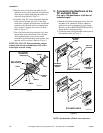
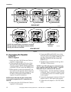
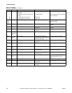
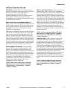
2. Locate the network board header on the back of
the machine. refer to Figure 4
NOTE: Stacked units will have two connectors.
Figure 3
COM1201N
TERMINAL
STRIP
WHITE
120
Ω 1/2 WATT
TERMINATING
RESISTOR
RED
BLACK
GREEN
RED
BLACK
560
Ω 1/4 WATT
BIAS RESISTOR
Figure 4
6
H
3
H
1
LO
W
ER
U
PPER/SIN
G
LE
5 4 3 2
1
1
23456
123456
123456
6
H3
H1
LO
W
ER
U
PPER
/SIN
G
LE
54321
1
23456
123456
CONTROL3a
NETWORK
INTERFACE
BOARD
BACK OF
MACHINE
SINGLE UNITS
STACKED UNITS
CONNECTOR
(210099)
NETWORK
BOARD
HEADER