


Installation and Safety Guide
13
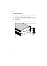
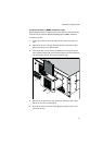
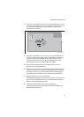
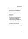
3. Connect the A feed -48 V wire to the screw terminal labelled “A -” on the
rear panel of the switch, and use a flat screwdriver to tighten the screw to
a torque of 0.5
to 0.8 Nm (4.4 to 7.1 lbf in). Ensure no wire strands
protrude from the terminal.
4. Connect the A feed 48 V return wire to the screw terminal labelled “A +”
on the rear panel of the switch, and use a flat screwdriver to tighten the
screw to a torque of 0.5
to 0.8 Nm (4.4 to 7.1 lbf in). Ensure no wire
strands protrude from the terminal. Note that the DC return input
terminal must be connected as Isolated DC return (DC-I).
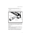
5. Use the same procedure to connect an additional power source, if
required, to the terminals labelled B.
6. Secure the tray cable near the rack framework using multiple cable ties to
minimize the chance of the connections being disturbed by casual contact
with wiring. Use at least four cable ties separated 10
cm (4 inches) apart
with the first one located within 15
cm (6 inches) of the terminal block.
7. Energise the DC power source to the switch.
The Fault LED should light for approximately 3 seconds as the switch runs
internal tests. If the LED remains lit, refer to the Rapier Switch Hardware
Reference for troubleshooting information.
8. Check that the Power LED on the front panel lights green.
If the LED fails to light, refer to the Rapier Switch Hardware Reference for
troubleshooting information.
48wDC_rear_panel
WARNING
This unit might have more
than one power input. To
reduce the risk of electric
shock, disconnect all power
inputs before servicing unit.
FOR CENTRALIZED DC
POWER CONNECTION,
INSTALL ONLY IN A
RESTRICTED AREA.
40-60VDC
4.5A MAX
DUAL INPUTS