


Page 35 | AlliedWare™ OS How To Note: EPSR
Counters
Counters
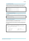
The EPSR counters record the number of EPSR messages that the CPU received and
transmitted. To display the counters, use the command:
show epsr=domain1 count
Master node in
a Complete
ring
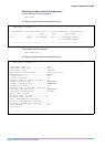
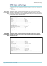
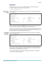
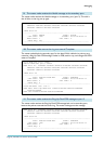
The following diagram shows the counters for a master node in a ring that has never had a
link or node fail.
Note that the node has generated
1
093 EPSR packets (and sent them out its primary port)
and has received the same number of EPSR packets (on its secondary port).
However, it is very common to see a few Link Down, Ring Down, and Ring Up entries in the
output of a ring that has never been in a Failed state. These messages are produced when you
first enable EPSR, if some ring nodes establish before others.
Transit N ode
in a ring that
had failures
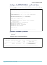
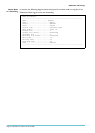
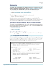
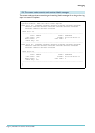
In contrast, the following diagram shows the counters for a transit node in a ring that has
been in a Failed state twice.
Here, the transit node has received
1
42
1
Health messages, which it will have forwarded on if
its ports were up. These messages do not show in the transmit counters because they are
transmitted by the switching hardware, not the CPU.
The node has also generated two Link-Down messages, indicating that on two separate
occasions one of its links has gone down.
EPSR Counters
------------------------------------------------------------------------
Name: domain1
Receive: Transmit:
Total EPSR Packets 1093 Total EPSR Packets 1093
Health 1092 Health 1092
Ring Up 1 Ring Up 1
Ring Down 0 Ring Down 0
Link Down 0 Link Down 0
Invalid EPSR Packets 0
------------------------------------------------------------------------
EPSR Counters
------------------------------------------------------------------------
Name: domain1
Receive: Transmit:
Total EPSR Packets 1425 Total EPSR Packets 2
Health 1423 Health 0
Ring Up 2 Ring Up 0
Ring Down 0 Ring Down 0
Link Down 0 Link Down 2
Invalid EPSR Packets 0
------------------------------------------------------------------------