


AT-GS950/8 Gigabit Ethernet WebSmart Switch Installation Guide
25
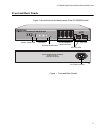
Network Topologies
This section describes two network topologies that you can create with the
AT-GS950/8 switch: a power workgroup and collapsed backbone. Both
types of topologies are described below.
Power
Workgroup
Topology
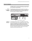
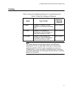
The topology shown in Figure 4 is commonly referred to as a power
workgroup topology. Each workstation or end node is connected directly to
a port on the AT-GS950/8 switch. Each end node has a dedicated data
link to the switch for the best performance and reliability results. The
devices can operate at 100 Mbps or 1000 Mbps.
Figure 4. Power Workgroup Topology
Collapsed
Backbone
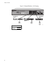
In the topology illustrated in Figure 5, an AT-GS950/8 switch connects
three Fast Ethernet switches that have Gigabit Ethernet uplinks. This type
of topology is often referred to as a collapsed backbone topology. In this
topology, the AT-GS950/8 switch functions as the focal point of the
network and transfers an Ethernet frame between the Fast Ethernet
switches only when the destination end node for the frame is on a different
switch than the end node that originated the frame. This topology reduces
the amount of unnecessary data traffic in each workgroup, freeing up
bandwidth and improving network performance.
915
Legend
100 Mbps
1000 Mbps